Powerwall 2 Lockout/Tagout
Hazards: Arc flash and electrical shock.
Safety and PPE:
- HRC2/CAT 2 arc-rated long-sleeved shirt (tucked in) and pants or coveralls
- Safety glasses (ANSI Z87.1 or EN 166)
- Class 0 electrical insulating rubber gloves with leather protectors (ANSI A4 cut resistant, ANSI A3 abrasion resistant, ASTM CAT2)
- Leather 6 in. boots with EH rating & composite toe
- CAT IV Multimeter (Fluke 1587 FC or equivalent) (rated for equipment voltage)
- Proving unit (Fluke PRV240 or equivalent)
-
Lockout/tagout kit (locks, tags, hasps, lock
box)
- Simple LOTOV: One person. One individually controlled lock. One tag with name and contact information, and breaker clamp
- Complex LOTOV: A complex LOTOV is required for multiple energy sources and multiple disconnecting means.
- Individually controlled locks & tags
- Breaker clamps
- Lock box or tree hasp
- The LOTOV Lead will be the person designated by the service visit assignment.
- The LOTOV form linked here is required for Tesla complex LOTOV.
- All individuals working on equipment are required to be included in the LOTOV.
General Equipment:
- T20 Torx driver
- Flat-head screwdriver
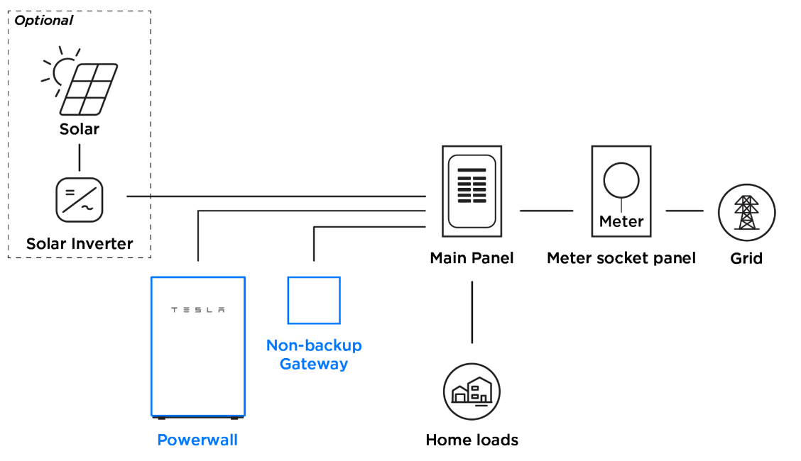
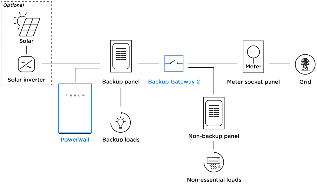
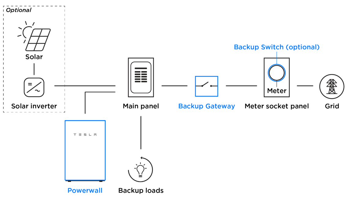
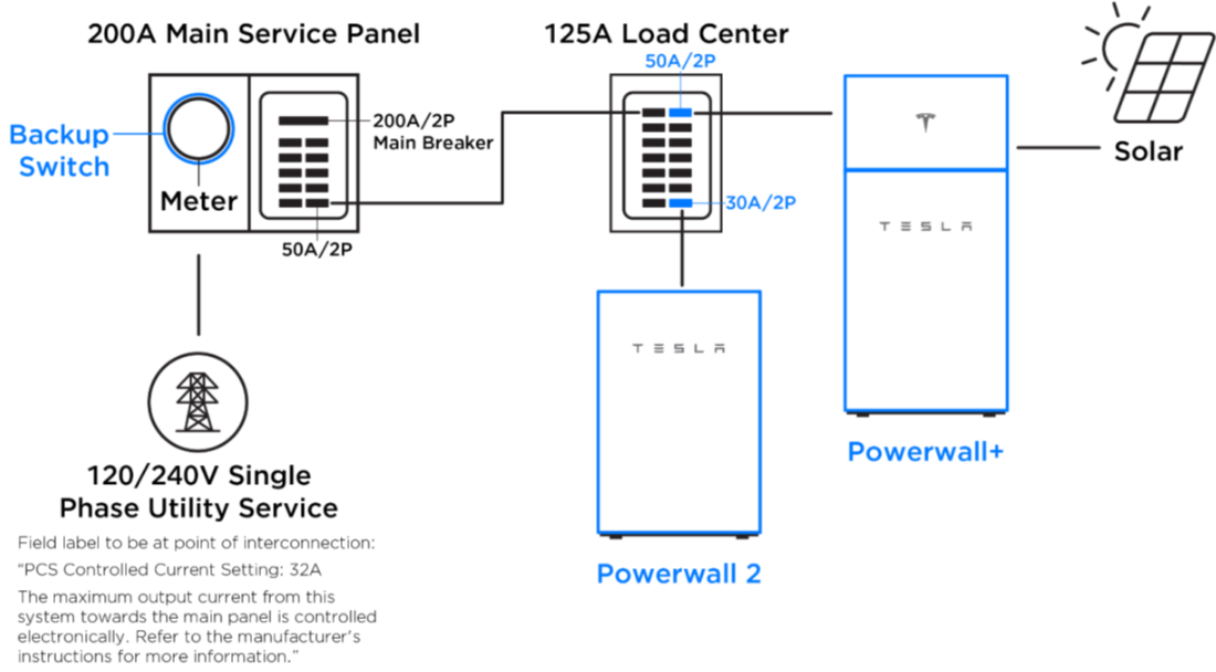
Figures showing variations of Powerwall 2 systems (non-exhaustive)
-
A Powerwall
2 inputs and outputs AC power at levels
that can be dangerous to an operator if not properly de-energized and isolated.
The Powerwall is connected to a home through a load center which contains live
voltage from the grid and any PV generation systems. Additionally, the
Powerwall's internal battery outputs power at high voltages.
Warning
While de-energizing the system, CAT 2 arc-rated PPE and Class 0 electrical insulating rubber gloves with leather protectors (ANSI A4 cut resistant, ANSI A3 abrasion resistant, ASTM CAT2) must be worn to protect against the electrical hazards that are present.
-
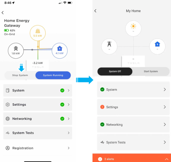
Turn off the system via the
setup app and ensure the app reflects that it has been turned off.
Note
Powering down the system this way will ensure all system components are shut down properly. The Powerwall should still be turned off with the switch on the side.
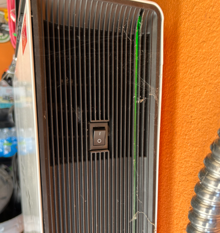
-
Power off the Powerwall with the
switch on the side of the unit. Apply a lock to the switch if the unit has a
locking on switch.
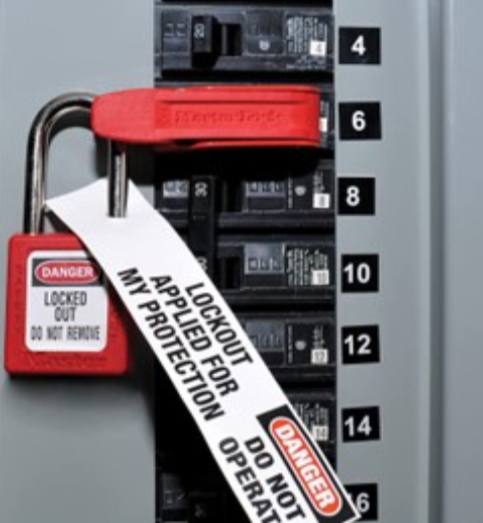
-
Isolate the Powerwall from the
home by turning off the dedicated PW breaker in the upstream load center. Apply
a breaker clasp and LOTO to the breaker.
Warning
All individuals that will be working on the Solar Inverter system must apply a Lock and Tag.
When more than one individual is working on the Solar Inverter system, all individuals must also sign on and off when applying and removing their lock. Use the LOTOV form linked here.
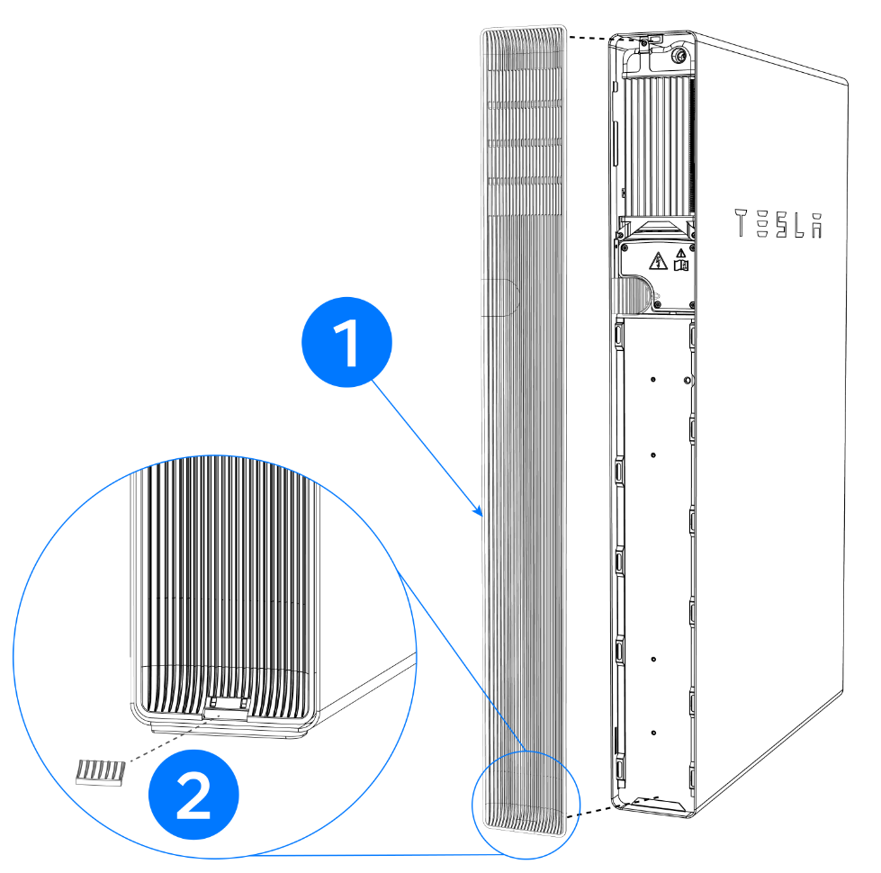
-
Remove the left side cover by
prying it outward with a Flat-head screwdriver.
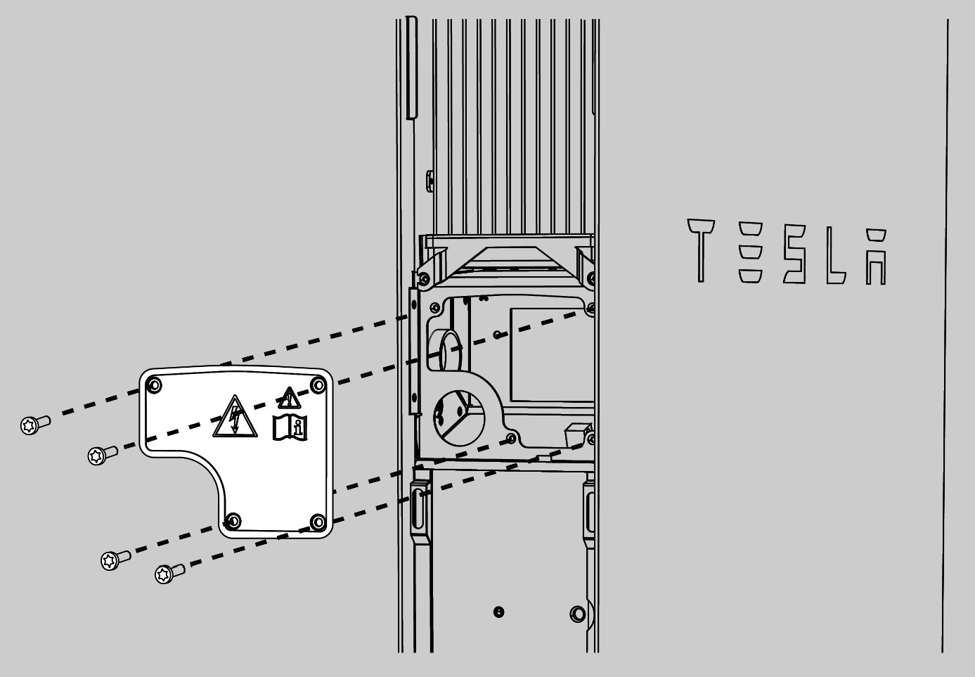
-
Remove the wiring compartment
cover by removing the four T20 fasteners.
- Put on Class 0 electrical insulating rubber gloves with leather protectors (ANSI A4 cut resistant, ANSI A3 abrasion resistant, ASTM CAT2). These gloves will be worn until Live- Dead – Live is completed and 0 voltage is verified.
-
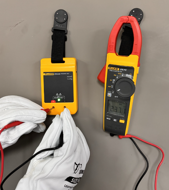
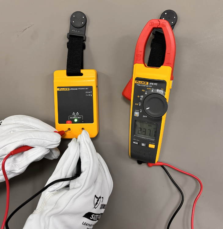
Set the Class IV Multimeter
(rated for equipment voltage) to measure AC voltage, and measure a known AC
source such as a Proving unit (Fluke PRV240 or equivalent). Ensure the measured
reading matches the known value. Switch both the multimeter and the proving unit
to DC voltage and repeat the test. Again ensure the readings match expected. If
either reading does not match what is expected, do not continue. Use another
multimeter and repeat the test.
-
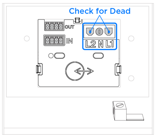
Check the AC terminals with a
multimeter. Remove the harness and test first the Powerwall side of the
connector: Check Phase to Phase, Phase to Neutral, and Phase to Ground voltages.
All voltages should be 0. Do not proceed if voltages read anything but 0 V.
Repeat the check again on the harness side of the connector, checking Phase to
Phase, Phase to Neutral, and Phase to Ground.
-
Set the Class IV Multimeter
(rated for equipment voltage) to measure AC voltage, and measure a known AC
source such as a Proving unit (Fluke PRV240 or equivalent). Ensure the measured
reading matches the known value. If the reading does not match what is expected,
do not continue. Use another multimeter and repeat the test again, starting over
with a live dead live.