This procedure is to be done
before actively working on a Powerwall+ to prevent arc flash and
electrical shock hazard.
Tools and
Equipment:
CAT 2 arc-rated long-sleeved
shirt (tucked in) and arc-rated pants
Safety Glasses (ANSI Z87
rated)
Class 0 insulated electrical
gloves with leather protectors or equivalent protectors (ANSI A4 cut
resistant, ANSI A3 abrasion resistant, ASTM CAT2)
Safety rated shoes with
leather upper
Class IV Multimeter (rated
for equipment voltage)
Proving Unit (Fluke PRV240 or
equivalent)
T20 Torx driver
Lockout/Tagout equipment:
Simple LOTOV: One
person, One individually controlled lock, One tag with name and
contact information, and breaker clamp
Complex LOTOV: A
complex LOTOV is required for multiple energy sources and multiple
disconnecting means.
Individually
controlled locks & tags
Breaker clamps
Lock box or tree
hasp
The LOTOV
Lead will be the person designated by the service visit
assignment.
The LOTOV Form is required for Tesla
complex LOTOV.
All
individuals working on equipment are required to be included
in the LOTOV.
Overview:
Residential systems are highly variable, de-energization procedures
may differ from site to site depending on the hardware the site has. Ensure you
understand the site architecture and the required de-energization procedure before
performing any work All steps of this procedure may not be applicable for all
systems due to this variability, but any applicable steps should be performed. If
you do not understand which steps are applicable please escalate to your manager for
assistance.
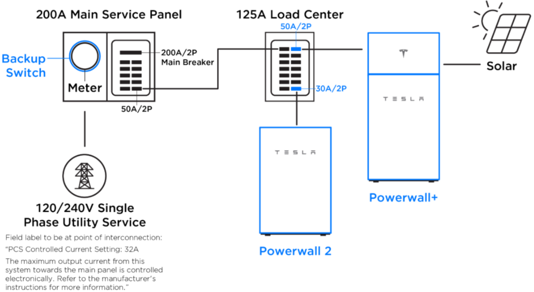
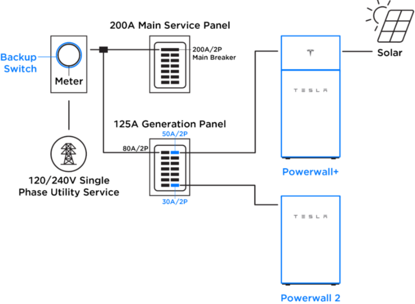
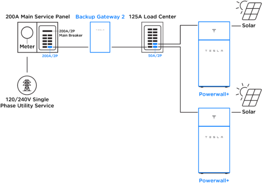
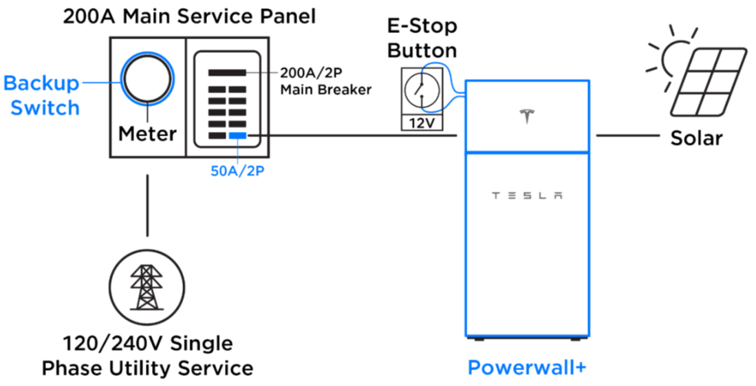
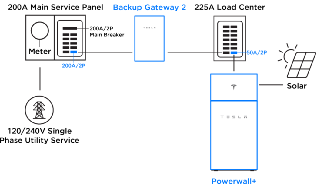
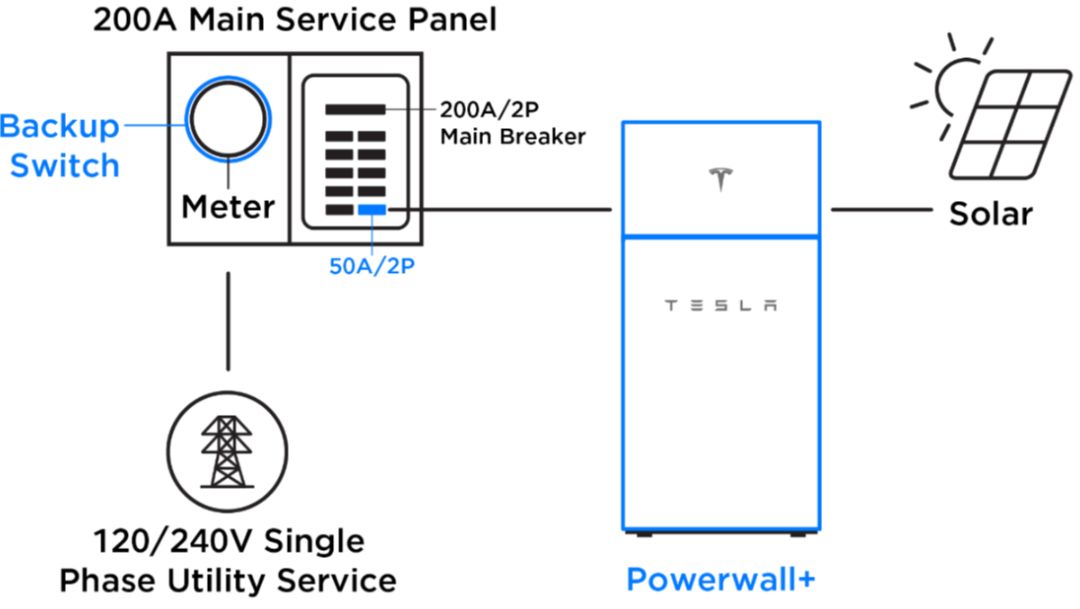
Figures showing variations
of systems containing a Powerwall+
(non-exhaustive)
The Inverter component of the
Powerwall+ system has 3 sources of incoming power that must be isolated to
perform work on the unit: AC Grid power, DC PV Power, and AC Powerwall
power.
Warning
While de-energizing the
system the proper PPE must be worn to protect against the electrical
hazards that are present. Ensure you have the proper PPE and are wearing
it correctly.
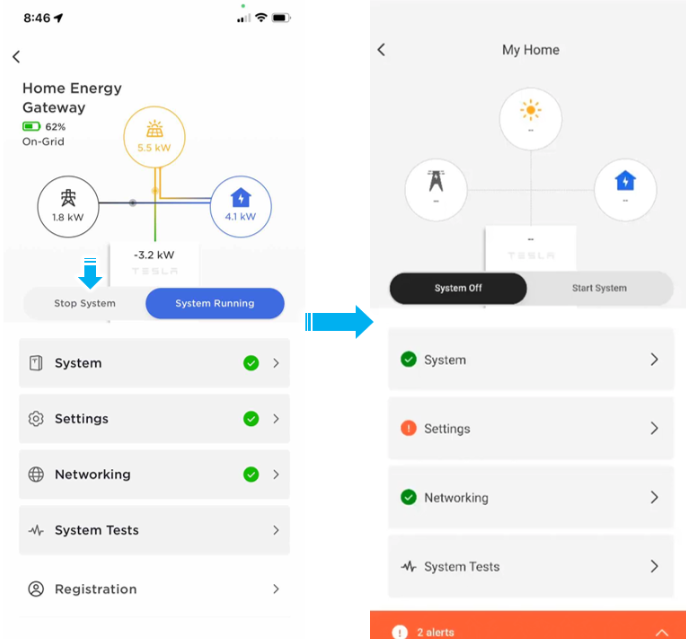
Turn off the system via the
setup app and ensure the app reflects that it's been turned off.
Note
Turning off via the system shutoff app will power
down all system components, this is important when a system has multiple
Powerwalls or other interconnected units.
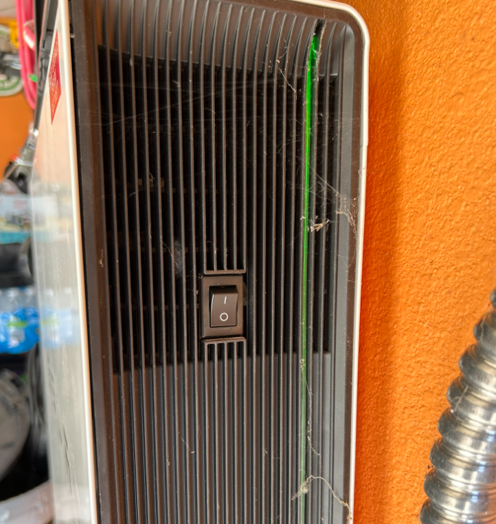
De-energize the Powerwall+ by
turning off the switch on the side of the Powerwall unit.
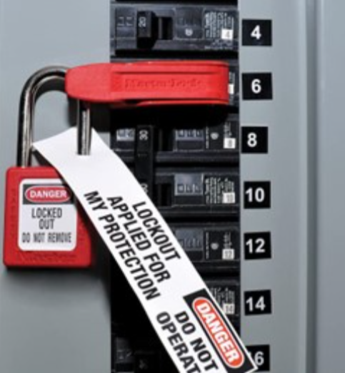
Isolate the Powerwall+ from the
load center/grid connection by disabling the breaker upstream of the PVI. Apply
a breaker clasp and LOTO to the breaker.
Note
This breaker may be in a backup load center, a main
load center, or in a backup gateway. The breaker that is directly upstream
of the Powerwall+ should be isolated or deenergized.
Warning
All individuals working on the Solar Inverter system must
apply a Lock and Tag. When more than one individual is working on the Solar
Inverter system, all individuals must also sign on and off when applying and
removing their lock. Use the LOTOV Form linked here.
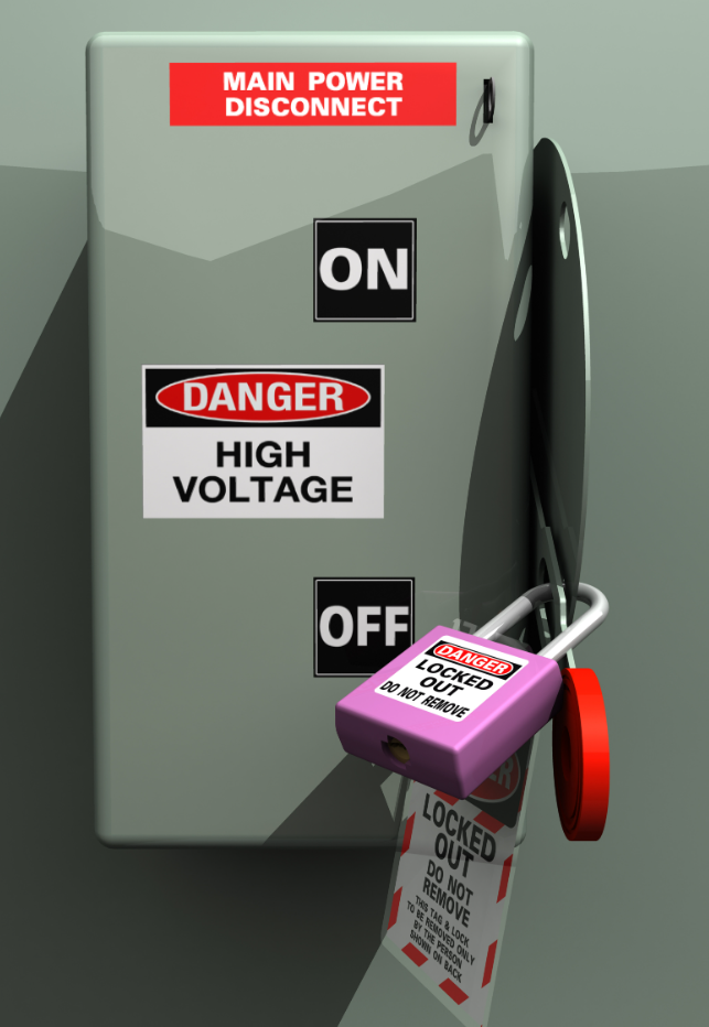
Isolate the PVI (Photovoltaic
Inverter) from the solar power. If there is a shutoff switch, turn it off and
apply a LOTO.
Note
This may not be present in all systems. If present,
this should only be done AFTER the Powerwall switch has been turned off.
Systems using MCIs (Mid-Circuit Interrupter) will be disconnected when the
system is disabled in the setup app and the Powerwall turned off.
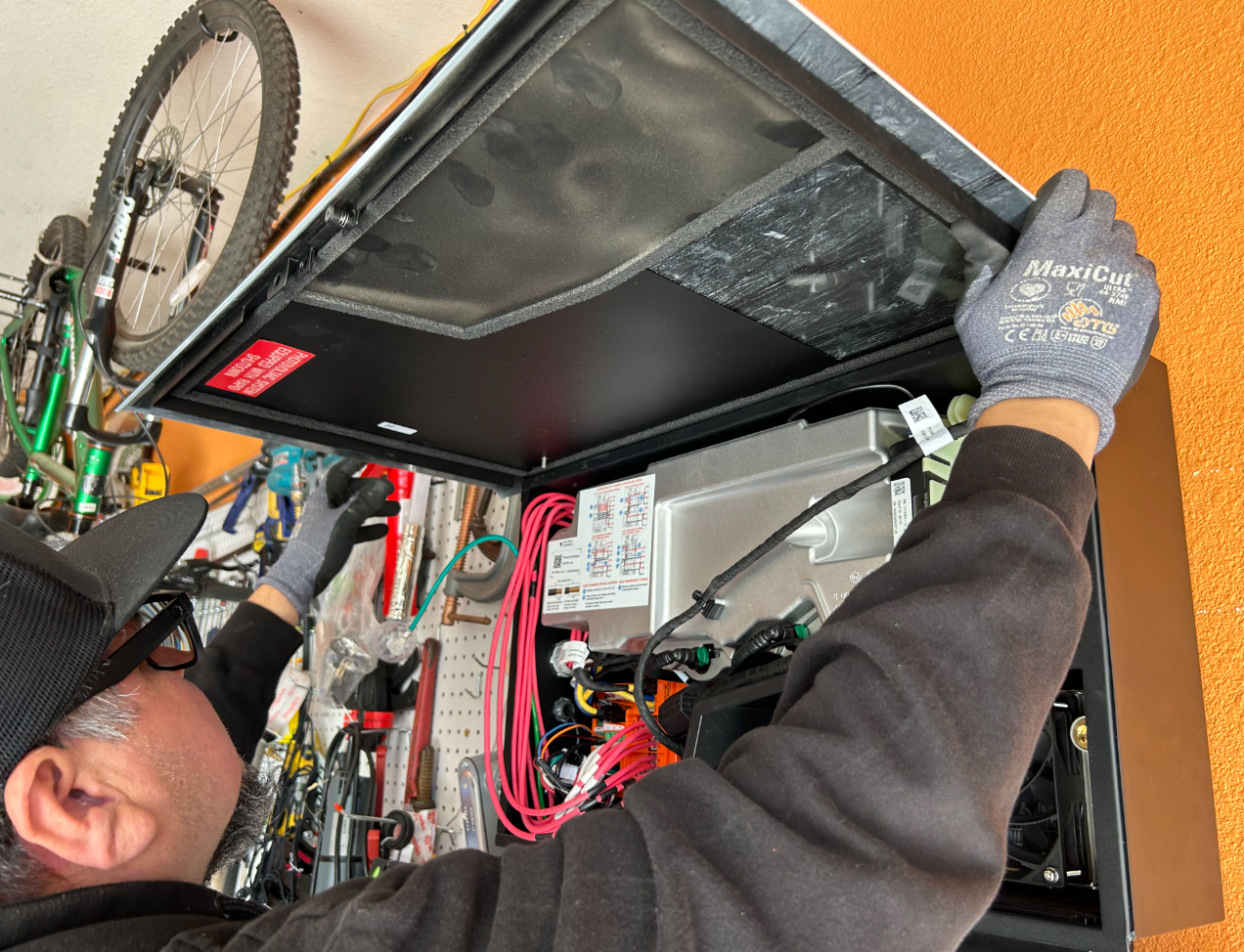
Open the door of the Solar
Assembly by depressing the latch and opening the door. Remove the ground wire
from the door by unscrewing the nut holding it. Slide the door to the right to
remove it from the hinges and set it aside.
Prepare a multimeter to check
the PVI for dead.
Put on Class 0 insulated
electrical gloves with leather protectors or equivalent protectors (ANSI A4 cut
resistant, ANSI A3 abrasion resistant, ASTM CAT2). These gloves will be worn
until Live- Dead – Live is completed and 0 voltage is verified.
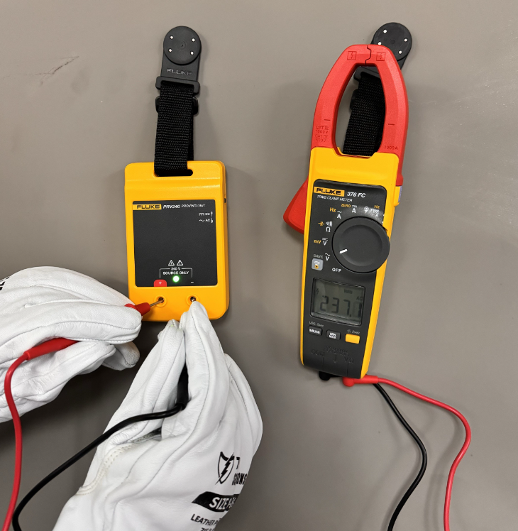
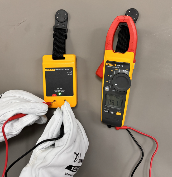
Set the multimeter (rated for
equipment voltage) to measure AC voltage, and measure a known AC source such as
a Proving unit (Fluke PRV240 or equivalent). Ensure the measured reading matches
the known value. Switch both the multimeter and the proving unit to DC voltage
and repeat the test. Again ensure the readings match expected. If either reading
does not match what is expected do not continue. Use another multimeter and
repeat the test.
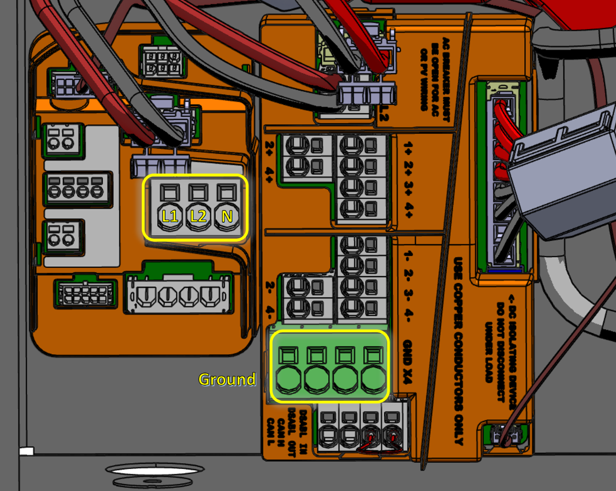
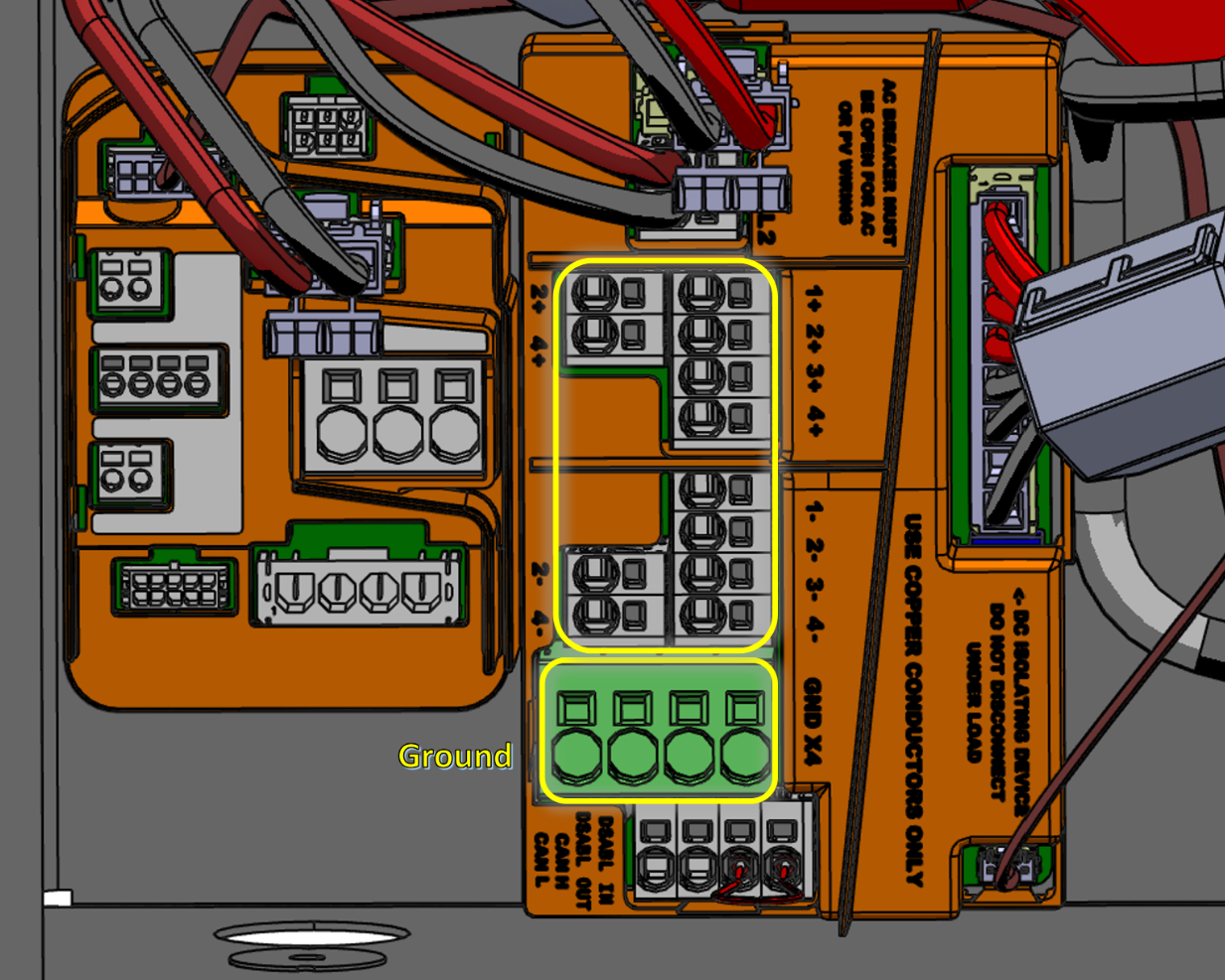
Set the multimeter to measure AC
voltage. Test the AC voltage between the L1, L2, N, and Ground relative to each
other. Check phase to phase, phase to neutral, and phase to ground. No voltage
should be more than 0V before proceeding with service. If you detect any AC
voltage, STOP and determine the cause. Do not proceed with work until the
voltage can be verified to be 0. Reach out to a supervisor if necessary.
Set the multimeter to measure DC
voltage. Test the DC voltage on each + PV string relative to their corresponding
-, as well as to ground. No voltage should be more than 0V before proceeding
with service. If you detect any DC voltage, STOP and troubleshoot before
continuing.
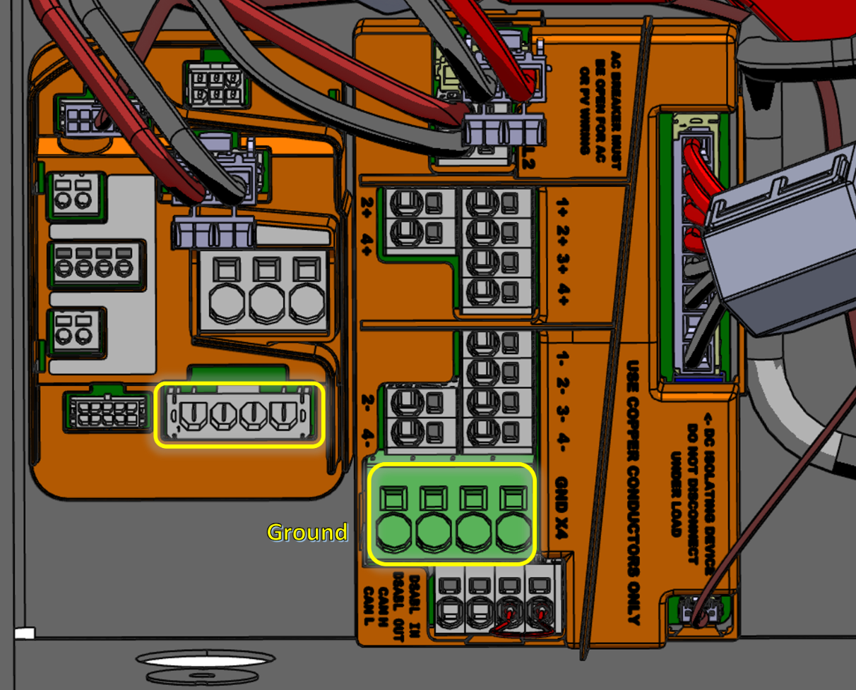
Switch the multimeter back to AC
voltage mode. Test the Powerwall connection AC voltage. Remove the harness from
the connector and probe inside of the connector. Measure phase to phase, phase
to neutral, and phase to ground. Repeat the same process with the harness
itself, measuring phase to phase, phase to neutral, and phase to ground. No
voltage should be more than 0V before proceeding with service. If you detect any
AC voltage, STOP and troubleshoot before continuing.
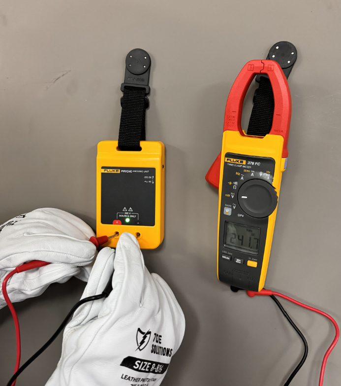
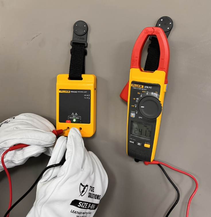
Set the multimeter (rated for
equipment voltage) to measure AC voltage, and measure a known AC source such as
a Proving unit (Fluke PRV240 or equivalent). Ensure the measured reading matches
the known value. Switch both the multimeter and the proving unit to DC voltage
and repeat the test. Again ensure the readings match expected. If either reading
does not match what is expected do not continue. Use another multimeter and
repeat the test.