Connect PV Strings to MPU
Warning
Never make or break PV connections under load.
Required Tools
- PPE
- Cut resistant gloves
- Safety Glasses (ANSI Z87 rated)
- Tape measure
- 9/16” socket
- Drill and/or socket wrench
- Small Philips and flat drivers
- Wire strippers and cutters
- MC4 extension cables
- Multimeter
- 12VDC source & 2-pin jump connector
- Grounding hardware (split bolts, ground rod clamps)
- Zip ties
- Hex key set
Step 1: Plan PV Stringing
- Each PV string must be made up of the
same type of solar panelNoteThis rule is always true for Tesla Solar Inverter and Powerwall 3, and should be assumed true for commercial solar inverters unless those inverter specifications explicitly state otherwise.
- Consider the inverter specifications:
- Tesla Solar Inverter and Powerwall 3 both have a nominal input voltage of 450 VDC with a DC input voltage range of 60 - 550 VDC
- String voltage should be calculated so that it does not exceed 550 VDC, but should preferably not exceed 500 VDC
- String Calculation Example 1:
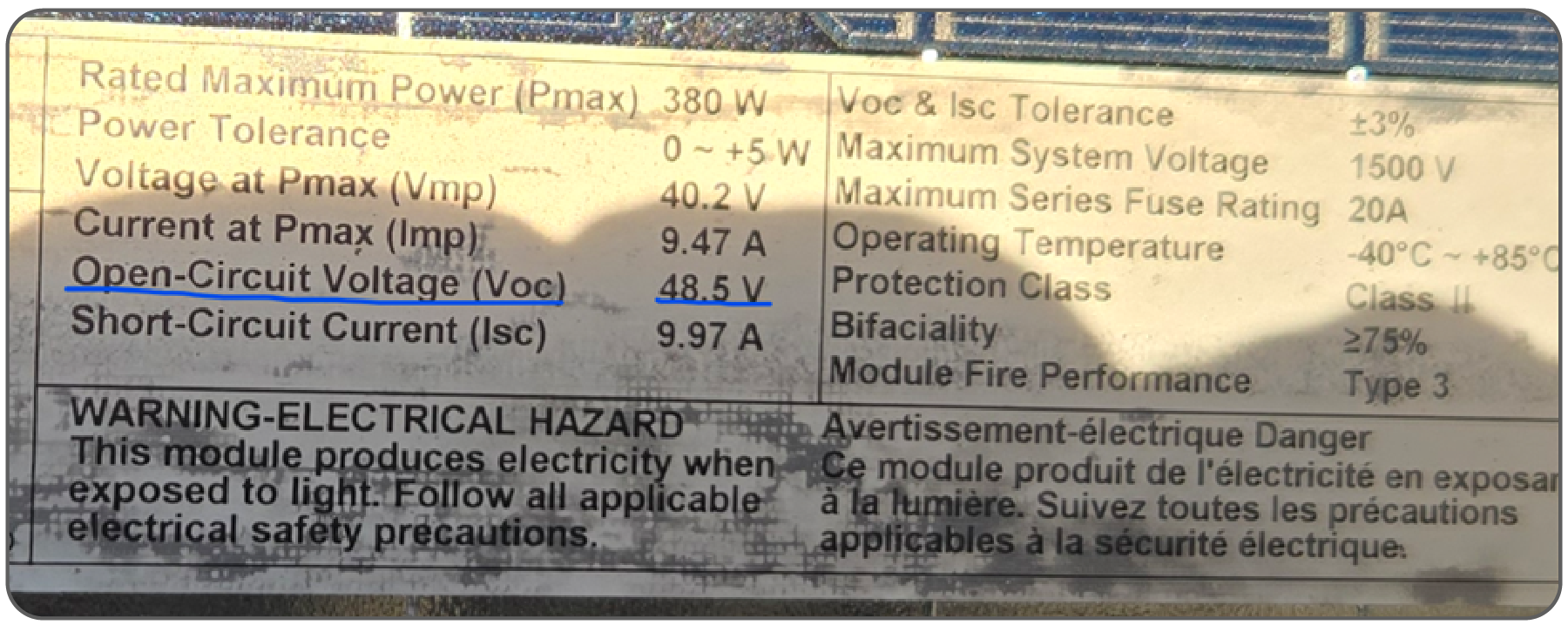
- This panel has an Open Circuit Voltage (VOC) of 48.5 VDC
- Maximum number of panels per string = 450 VDC
- 450 VDC / 48.5 VDC = 9.27 panels per string
- 10 panels per string provides a string voltage of 485 VDC, which is less than 500 VDC, and is therefore acceptable
- String Calculation Example 2:
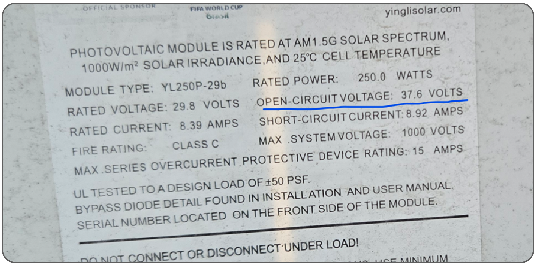
- This panel has an Open Circuit Voltage (VOC) of 37.6 VDC
- Maximum number of panels per string = 450 VDC
- 450 VDC / 37.6 VDC = 11.96 panels per string
- 12 panels per string provides a string voltage of 451.2 VDC, which is less than 500 VDC, and is therefore acceptable
- Plan the solar panel layout for the available area
- Identify 500 ft2 of dry, flat land that will ideally not be subjected to flooding
- For optimal racking usage, arrange panels in a 5 x 6 panel array (other configurations will use more ground mounts)
- Be aware of traffic patterns near where the solar panels will be arranged, and prepare the area as needed with barriers/cones
Step 2: Lay Out Solar Racking and Panels
Note
See the UNIRAC Install Manual (download RM10 EVO Install Manual
from Product Support Documents) for complete racking installation
instructions.
- Don't overtighten the racking equipmentCAUTIONOvertightening racking equipment may lead to cracked panels.
- For a 5 x 6 panel array, 42 bays and 144 clips/bolts are requiredNoteBolts and clips are not needed for the front or rear-most rows
Step 3: Connect Solar Panels in String
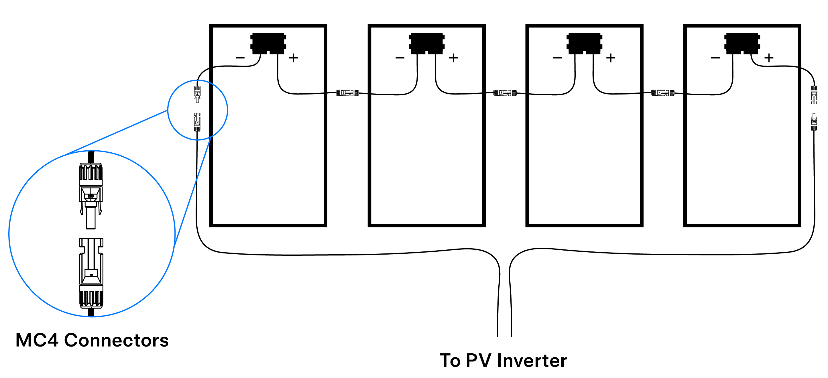
- Connect the solar panels for the designated string in series, connecting the male MC4 connector of one panel to the female MC4 connector of the next panel.
- Connect either end of the string to the inverter.
CAUTION
Do not connect the MC4 connectors at either end of the string directly
to each other. This will result in permanent damage to the PV array.
Important notes on connecting solar panels:
- Older SMA inverters only have one MPPT, and all strings must have the same number of panels and be of the same type
- Inspect connectors as panels are being set to ensure they are secure and in good condition
- Use MC4 extension cables for longer home runs if needed
- Measure the open-circuit voltage of
each string
- Open circuit voltage should be approximately VOC * # of panels (e.g. 45V * 10 = 450V)
- Ground the PV array
- Connect the racking/frames of the array to a local earth electrode or to an earth terminal block in MPU breaker panel
Step 4: Ground the MPU
- If a local ground grid is available, utilize 10 AWG ground wire to ground the MPU to the local ground grid
- If a local ground grid is not available, ground the MPU using a grounding rod per local requirements (typically driving an 8 ft ground rod into soil)
- Connect the earth terminal block of the MPU breaker panel to an earth electrode or terminal block in breaker panel on site
Step 5: Connect Strings to Solar Inverter
Warning
Never make or break PV connections under load. Always confirm the solar
inverter / Powerwall 3 is powered OFF and is not connected to AC power, and there is no voltage on the PV
inputs before connecting / disconnecting wiring.
- Confirm the inverter is powered OFF:
- For Tesla Solar Inverter, confirm the Solar Inverter breaker is open (OFF).
- For Powerwall 3, confirm the switch on the left side of the unit is OFF, then confirm the Powerwall 3 breaker is open (OFF).
- For older third party solar inverters, confirm the DC disconnect is open (OFF), then confirm the inverter breaker is open (OFF).
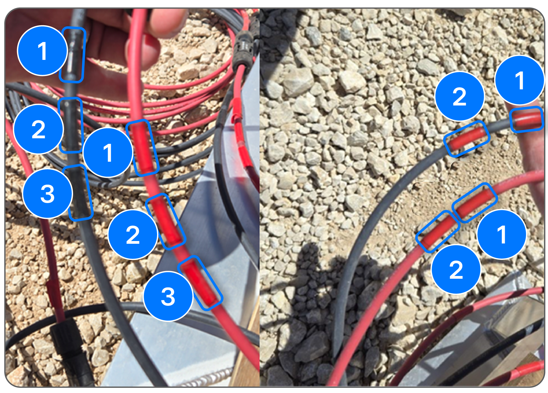
- Label each string by either placing bands of tape of the string (1 band of tape =
String 1), or by placing number tape on the string
- Connect the strings to the inverter:
- For Tesla Solar Inverter, connect each string's conductors to the
appropriate positive and negative terminals (e.g. connect String 1 to MPPT 1+ and 1-):
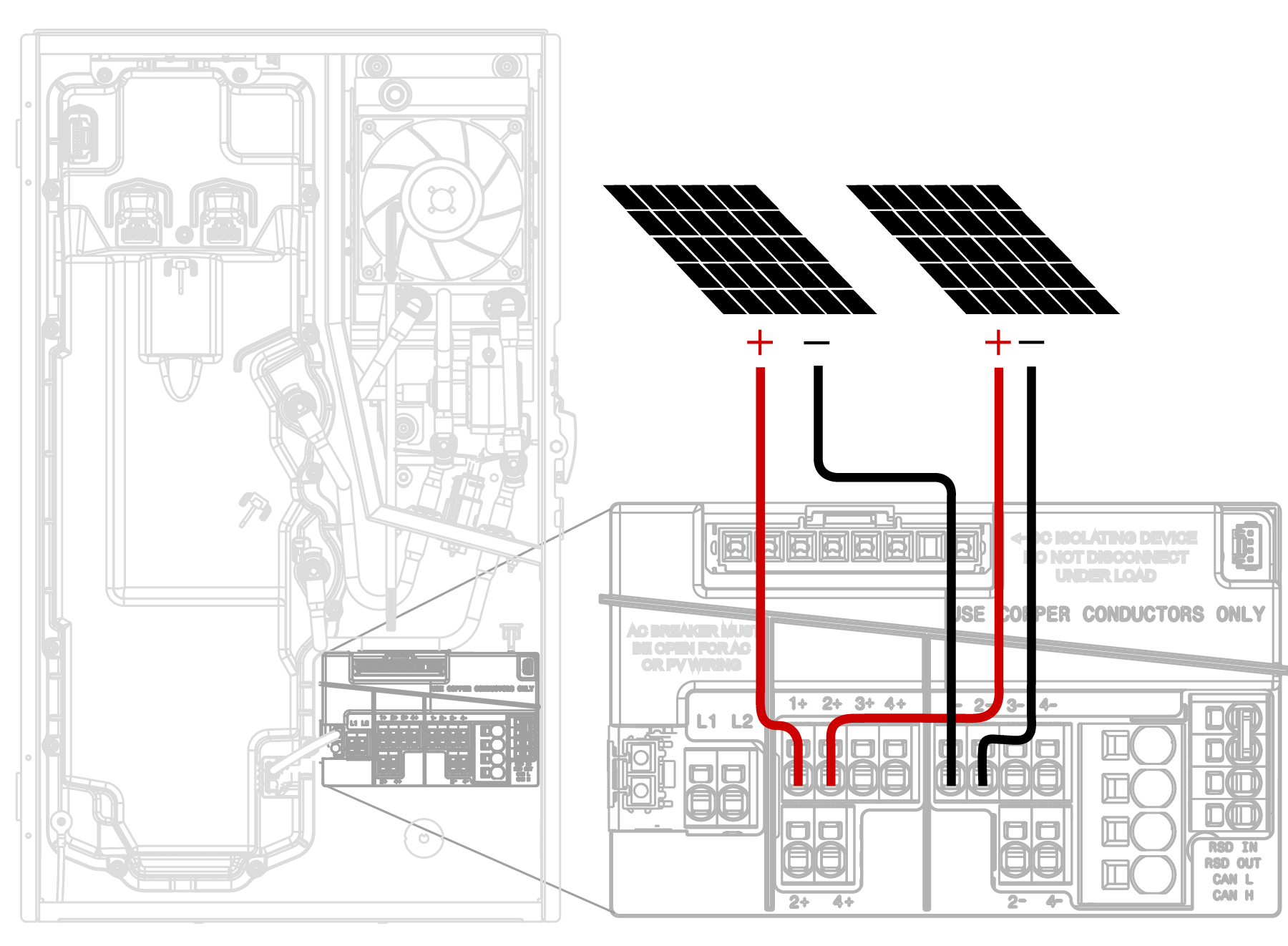 NoteWhere the DC input current exceeds an MPPT rating of 13 A, jumpers can be used to allow a single MPPT to intake strings with a total DC input current of up to 26 A. 4-inch MPPT paralleling jumpers are included in the Solar Inverter accessory bag. See the Tesla Solar Inverter installation manual for more information.
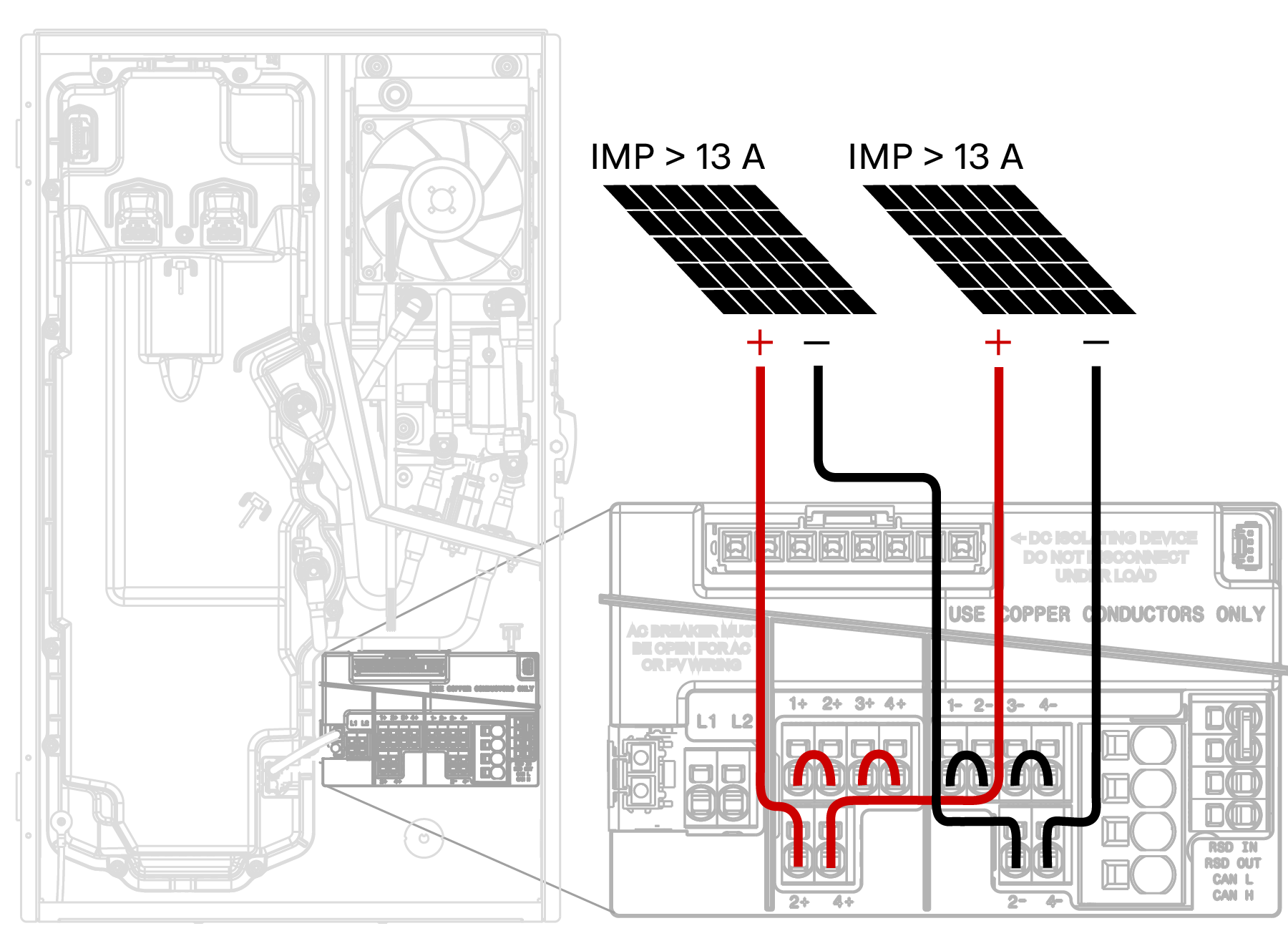
- For Powerwall 3, connect each string's conductors to the appropriate positive and negative
terminals (e.g. connect String 1 to MPPT 1+ and 1-), noting that the order of the PV
conductors depends on the Powerwall 3 variant:
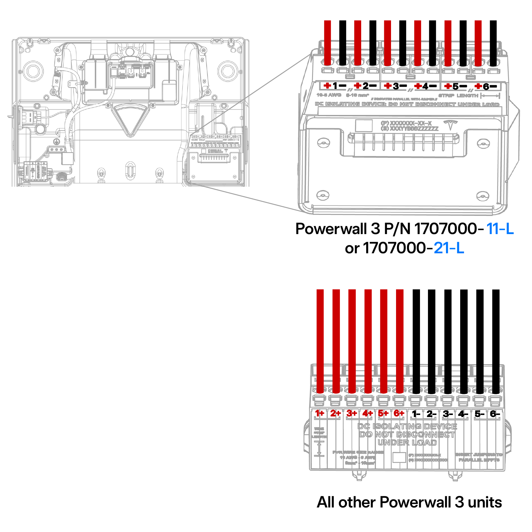 NoteWhere the DC input current exceeds an MPPT rating of 13 A, jumpers can be used to allow a single MPPT to intake strings with a total DC input current of up to 26 A. Jumpers are included in the Powerwall 3 accessory bag. See the Powerwall 3 installation manual for more information.
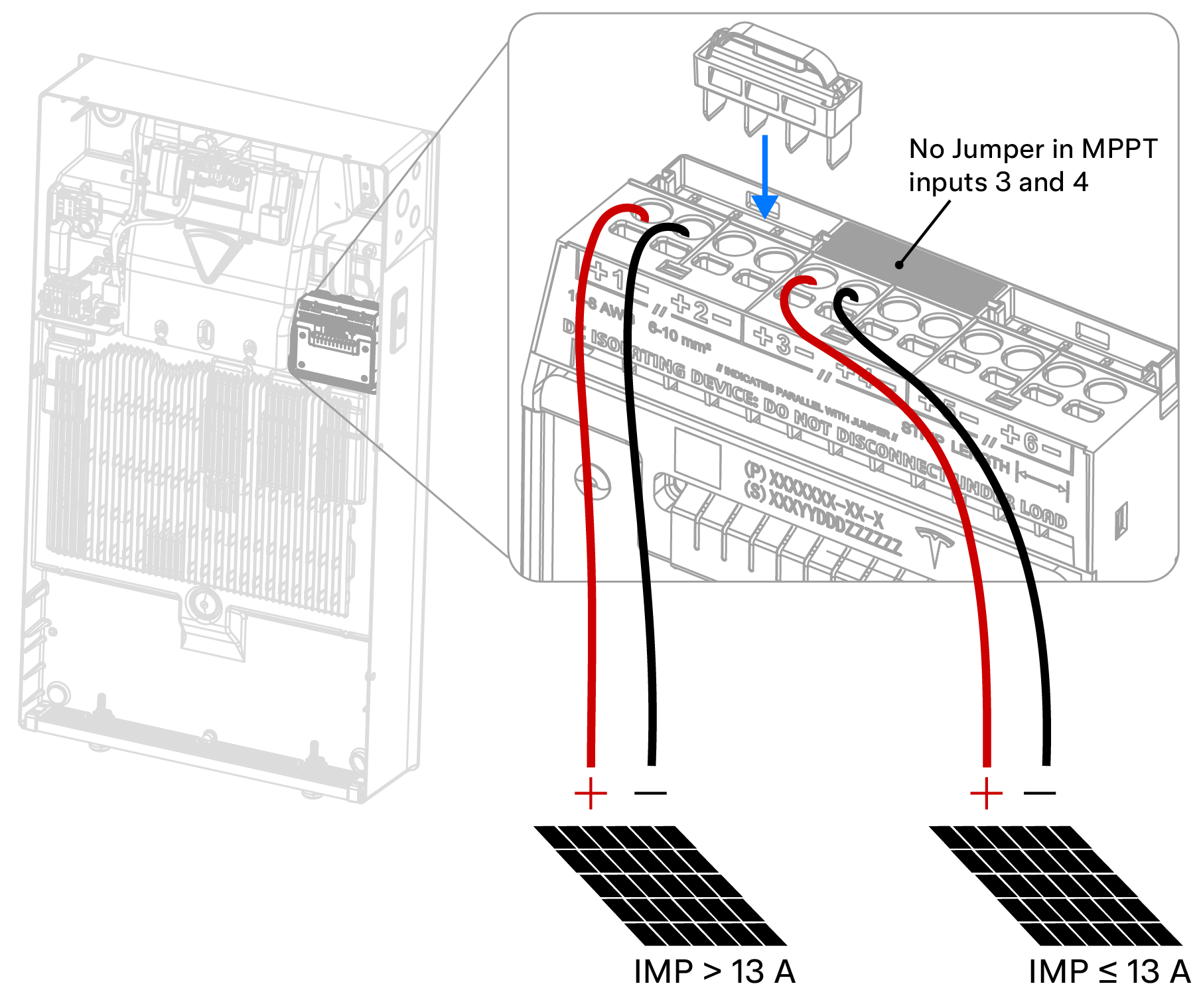 NoteWhen the Powerwall 3 product label lists 15 A IMP, jumpers can be used to parallel MPPT to double the total PV input current capacity to 30 A.
 - For other third party inverters, connect the PV strings per the manufacturer's instructions.
- For Tesla Solar Inverter, connect each string's conductors to the
appropriate positive and negative terminals (e.g. connect String 1 to MPPT 1+ and 1-):
Turn the MPU ON
- For MPU variant 1 with an SMA inverter, turn the DC disconnect ON. The inverter screen and LEDs should turn on when DC power is provided.
- Turn all Powerwall breakers ON, then turn the Powerwall switches ON.