Connect Powerwall 3 to the appropriate breaker size
depending on the desired power / current output (configured in Tesla One):
Table 1. Maximum Continuous Power /
Current Options
Maximum Continuous
Current
Power Output (AC)
Breaker (Overcurrent
Protection)
48 A On-grid 64 A Off-grid*
11.5 kW On-grid 15.4 kW Off-grid*
80 A*
48 A
11.5 kW (default)
60 A
41.7 A
10 kW
60 A
31.7 A
7.6 kW
40 A
24 A
5.8 kW
30 A
*Powerwall 3 can only provide 15.4 kW when
off-grid and when there is
sufficient solar; when the
system is on-grid, and/or when solar production is insufficient, Powerwall 3 will provide 11.5 kW. If
enabling this feature, Powerwall 3 must be installed with an 80 A
breaker and appropriately sized conductors.
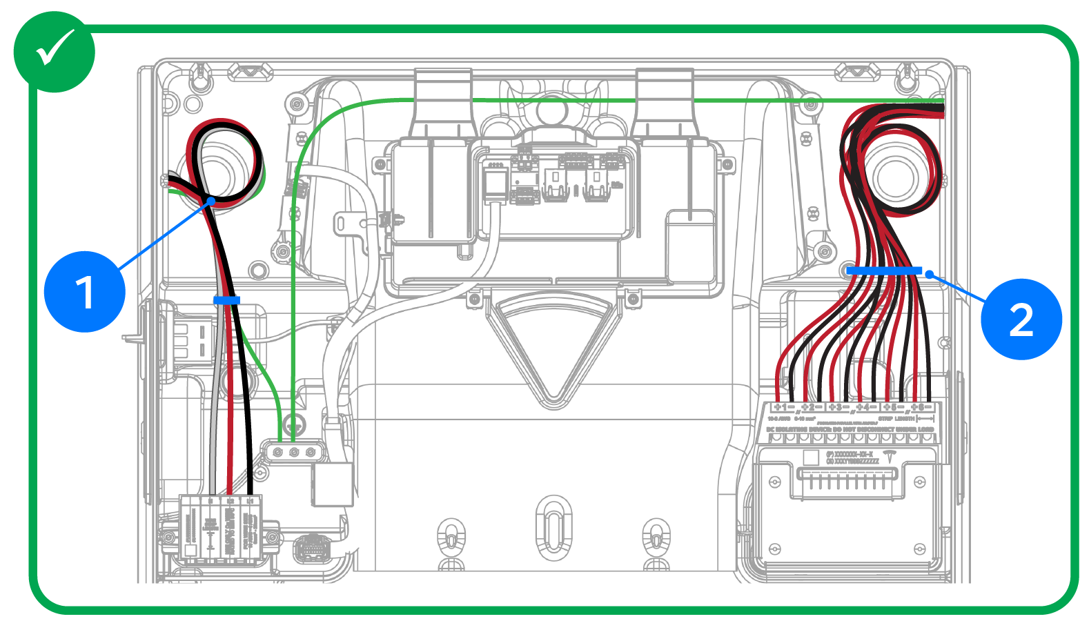
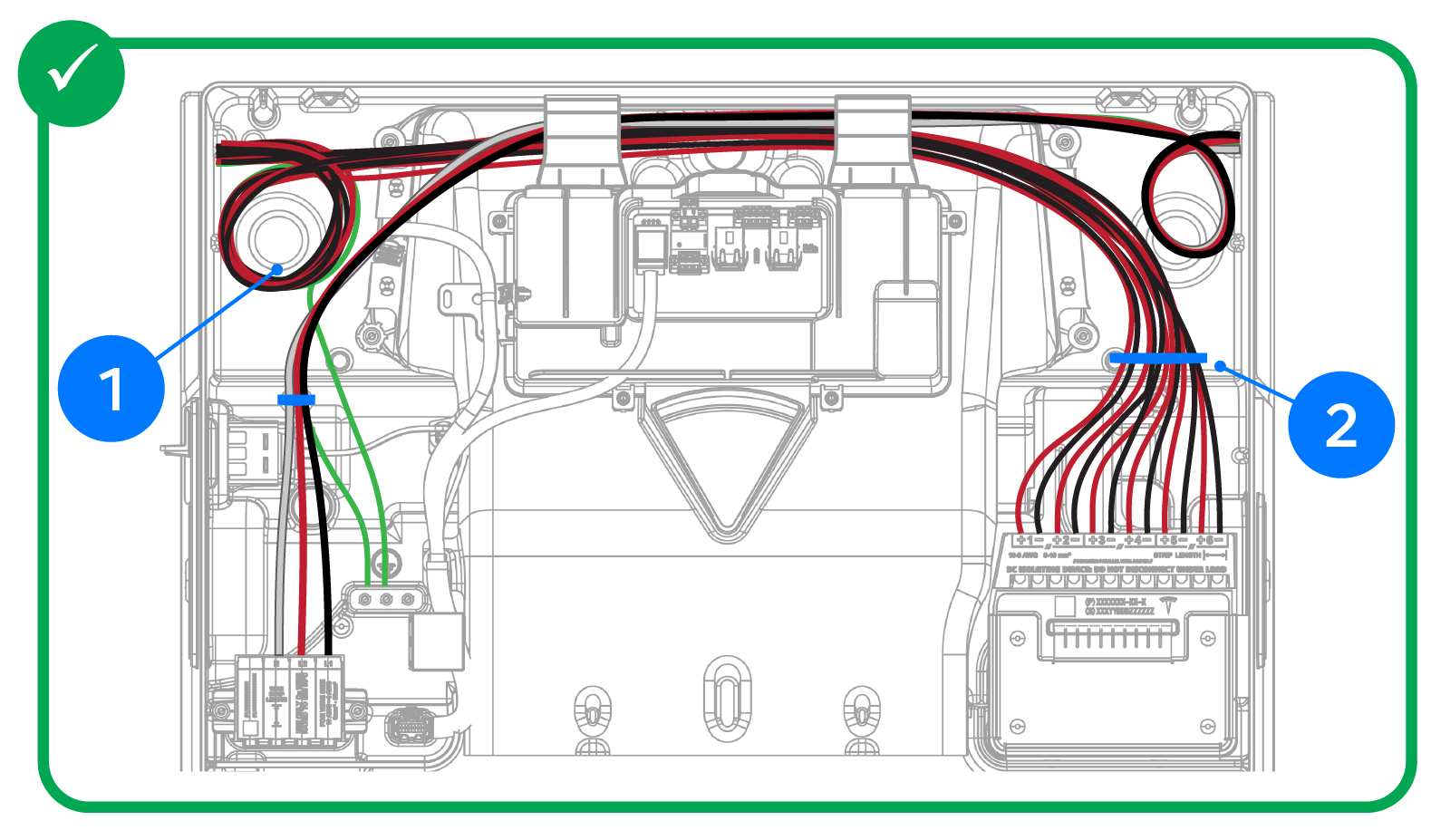
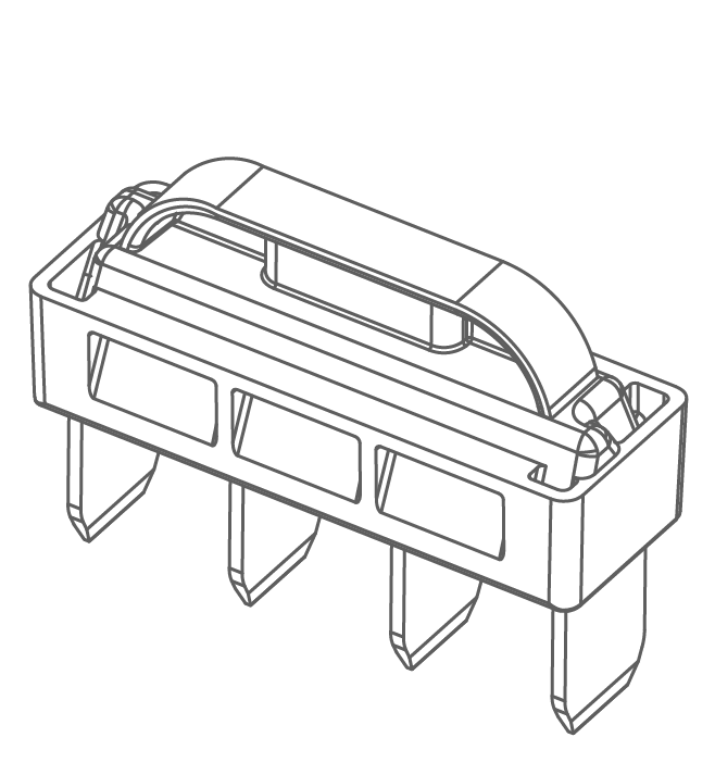
1
Ground terminals: 12-4 AWG (4-25 mm2),
torque to 35 in-lb with Torx T20
2
N / L2 / L1: 10-4 AWG (6-25 mm2), use
up to 4.5 mm (3/16 inch) cabinet / electronics tip
screwdriver
3
Gather conductors in provided cable
tie
4
Leave a service loop
CAUTION
If using a fuse
as the Powerwall 3 overcurrent protection
device, it must be a Class RK1 Fast Acting fuse. Use one of the following fuses
or equivalent:
Fuse Type
Manufacturer
Part Number
80 A Fast-Acting Fuse, Class RK1, >=
250VAC, CLF
Littelfuse
KLNR080
Eaton / Bussmann
KTN-R-80
Mersen / Ferraz Shawmut
A2K80R
60 A Fast-Acting Fuse, Class RK1, >=
250VAC, CLF
Littelfuse
KLNR60
Eaton / Bussmann
KTN-R-60
Mersen / Ferraz Shawmut
A2K60R
40 A Fast-Acting Fuse, Class RK1, >=
250VAC, CLF
Littelfuse
KLNR40
Eaton / Bussmann
KTN-R-40
Mersen / Ferraz Shawmut
A2K40R
30 A Fast-Acting Fuse, Class RK1, >=
250VAC, CLF
Littelfuse
KLNR30
Eaton / Bussmann
KTN-R-30
Mersen / Ferraz Shawmut
A2K350
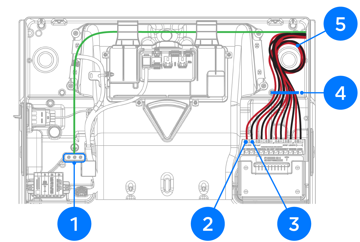
Make Powerwall 3 PV Power Connections
Warning
Turn the Powerwall 3 Enable switch OFF before doing any wiring.
1
Ground
terminals: 12-4 AWG (4-25 mm2),
torque to 35 in-lb with Torx T20
2
MPPT Positive PV inputs: 10-6 AWG (6-16
mm2)
Use up to 4.5 mm (3/16 inch)
cabinet / electronics tip screwdriver
3
MPPT Negative PV inputs: 10-6 AWG (6-16
mm2)
4
Gather
conductors in provided cable tie
5
Leave a service
loop
Important Notes on Installing MPPT
Jumpers:
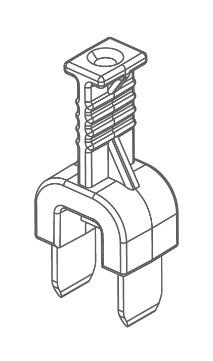
The jumpers provided in the Powerwall 3 accessory bag can only
be used with the Powerwall 3 model they shipped with:
Powerwall 3
Part Numbers
Jumper Part Number
Jumper Image
1707000-11-L or
170700-21-L
2009322-xx-y
All other Powerwall 3
part numbers
1784893-xx-y
CAUTION
These jumpers are not interchangeable. Only install
the jumpers that ship with the unit.
Jumpers can be used when
IMP > 13A.
Use jumpers to allow a single MPPT to intake strings with a total IMP up to 26A
Land the combined circuit (2
strings in parallel = 1 circuit) or string with IMP greater than 13A
in the terminal and connect the jumper from:
MPPT 1 to MPPT 2
MPPT 5 to MPPT 6
MPPT PV inputs 3 and 4 cannot
be combined and are closed from the factory
Do not use jumpers on Solar
Roof jobs - you cannot parallel more than two strings so combined circuit
IMP will
always be less than 13A DC
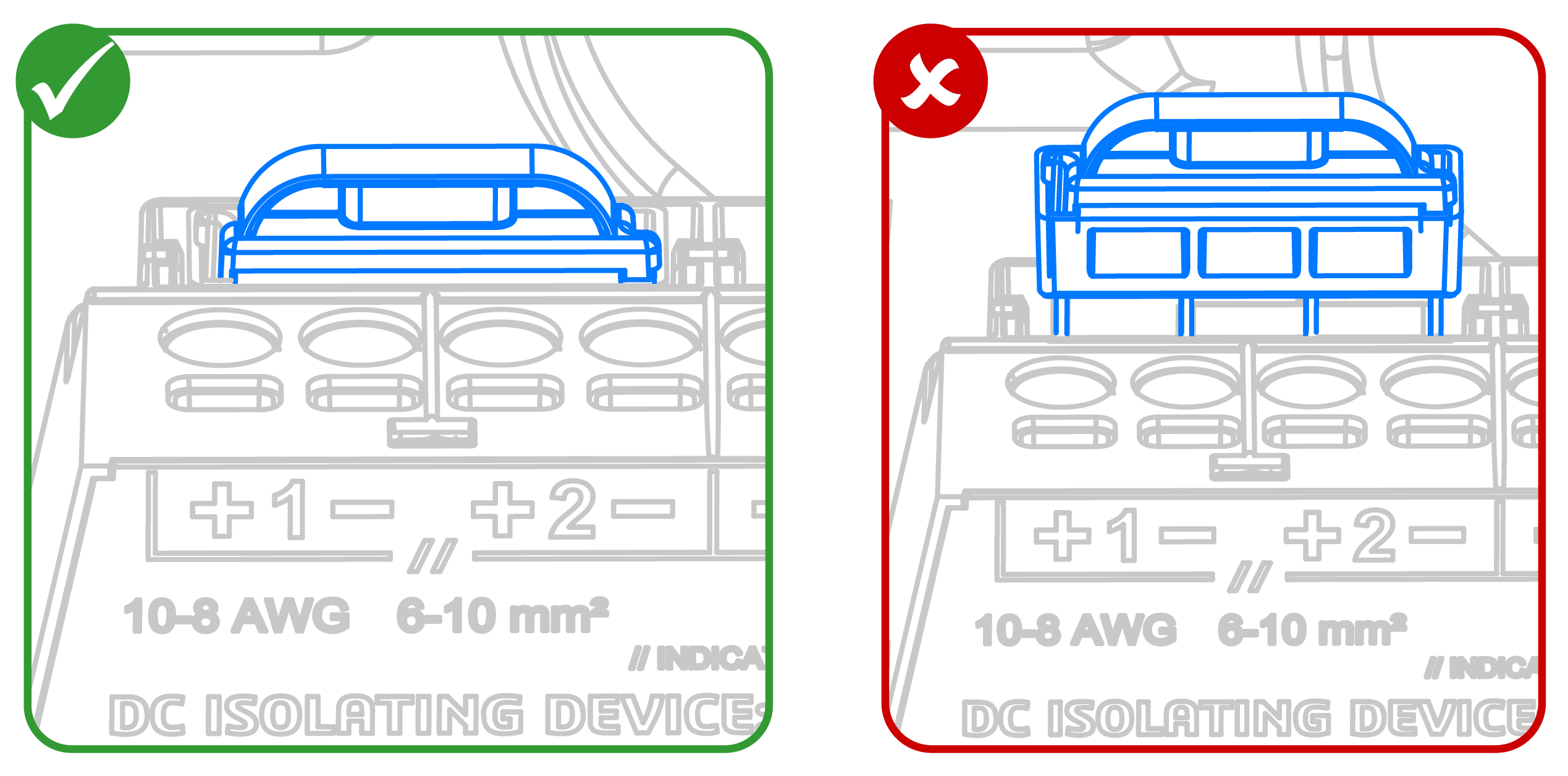
Ensure each jumper is fully
seated in the connector!
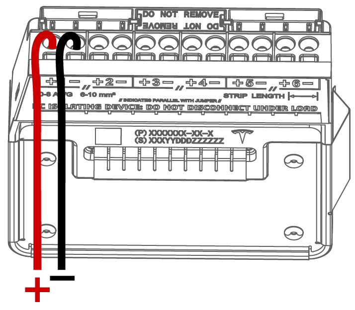
Figure 1. Example PV Wiring
Configuration: Up to (6X) Independent Strings where IMP of Each String <
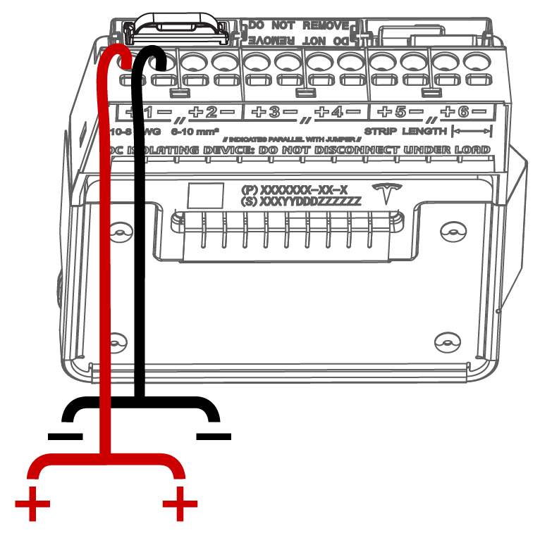
13AFigure 2. Example PV Wiring
Configuration: Up to (6X) Pairs of Combined Strings where IMP of Each Combined
Circuit > 13A (Jumpers Required)
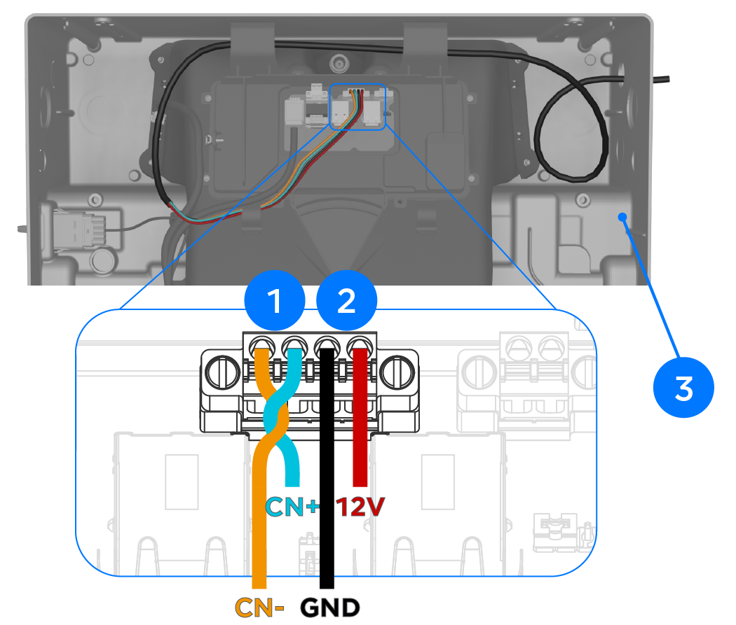
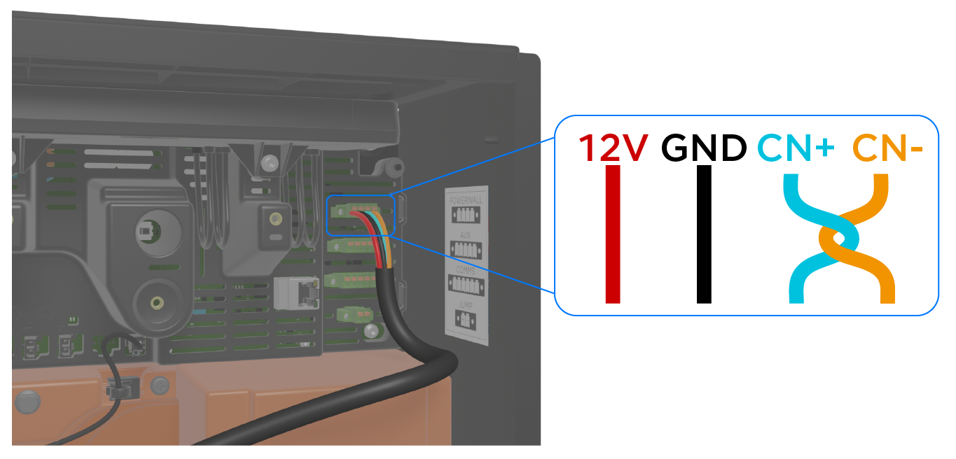
Connect Powerwall 3 to the Backup Switch / Backup
Gateway 2 / Gateway 3
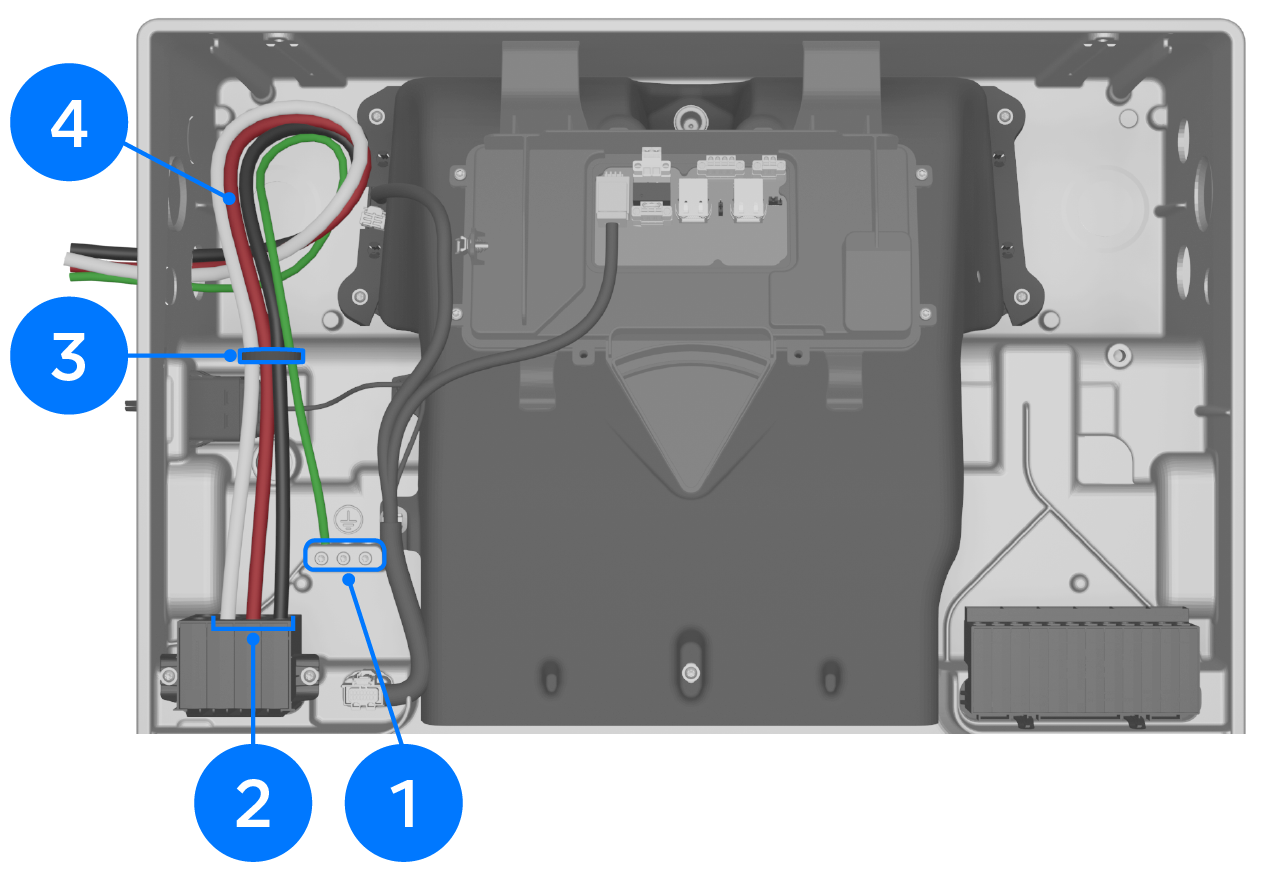
1
CN- (CAN LO): 24-16 AWG (0.2-1.5 mm2)
Use up to 3 mm (3/32 inch)
cabinet / electronics tip screwdriver
CN+ (CAN HI): 24-16 AWG (0.2-1.5 mm2)
2
GND: 24-16 AWG (0.2-1.5 mm2)*
12V+: 24-16 AWG (0.2-1.5 mm2)*
3
Leave a service
loop
*18 AWG is the recommended minimum wire gauge due to potential voltage drop on long
wire runs.
Note
CN- and CN+ must be twisted pair.
Note
The wire order for Backup Switch /
Backup Gateway 2/ Gateway 3 is not the same as the wire order for Powerwall 3.
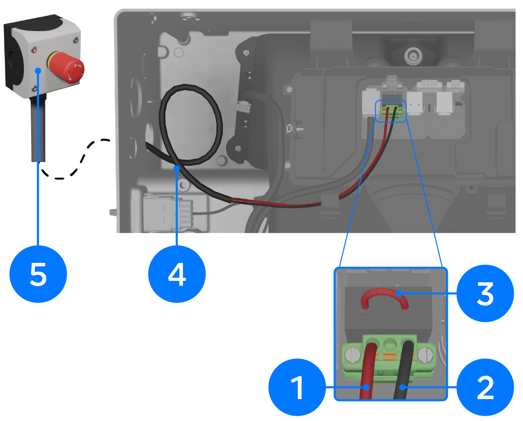
Install System Shutdown Switch Where Required
CAUTION
The System Shutdown
Switch must be connected to Powerwall 3. Do not connect it to the
Backup Gateway 2 as it will not work.
1
Rapid Shutdown IN: 24-16 AWG (0.2-1.5 mm2)
Use up to 3 mm (3/32 inch)
cabinet / electronics tip screwdriver
2
Rapid Shutdown OUT: 24-16 AWG (0.2-1.5 mm2)
3
Remove RSD
jumper when installing System Shutdown Switch; otherwise, leave
installed
4
Leave a service
loop
5
Connect the RSD
wiring to a suitable DC switch (see the Powerwall 3 with Backup Gateway
2,
Backup Switch, or
Gateway 3
installation manual for full details)
 CAUTIONThese jumpers are not interchangeable. Only install the jumpers that ship with the unit.