Multi-Powerwall 3 Installations
Powerwall 3 can be installed with additional Powerwall 3 units for additional solar and storage capabilities, and/or with Powerwall 3Expansion units for additional storage (kWh).
| Maximum Number of Powerwall 3 Units | Up to (4)Powerwall 3 units |
| Leader Powerwall 3 | The Powerwall 3 connected to
the via 12V / CAN
communication wiring is designated as the Leader Powerwall 3 Note The system is
commissioned by connecting to the Leader Powerwall 3. |
| Follower Powerwall 3 | Any Powerwall 3 other than the Leader is connected via inter-Powerwall Ethernet wiring and is designated as a Follower unit |
| Maximum Number of Expansion Units | Up to (3) Expansion units (for a
maximum total of (7) units) Note Expansion units must
be connected to the Leader Powerwall 3; they will
not function if connected to a Follower unit. |
| Powerwall 3 Compatibility with Expansion Units | Powerwall 3 units with Tesla P/N 1707000-xx-J or greater are compatible with Expansions |
System Shutdown Switch with Multiple Powerwall 3 Units
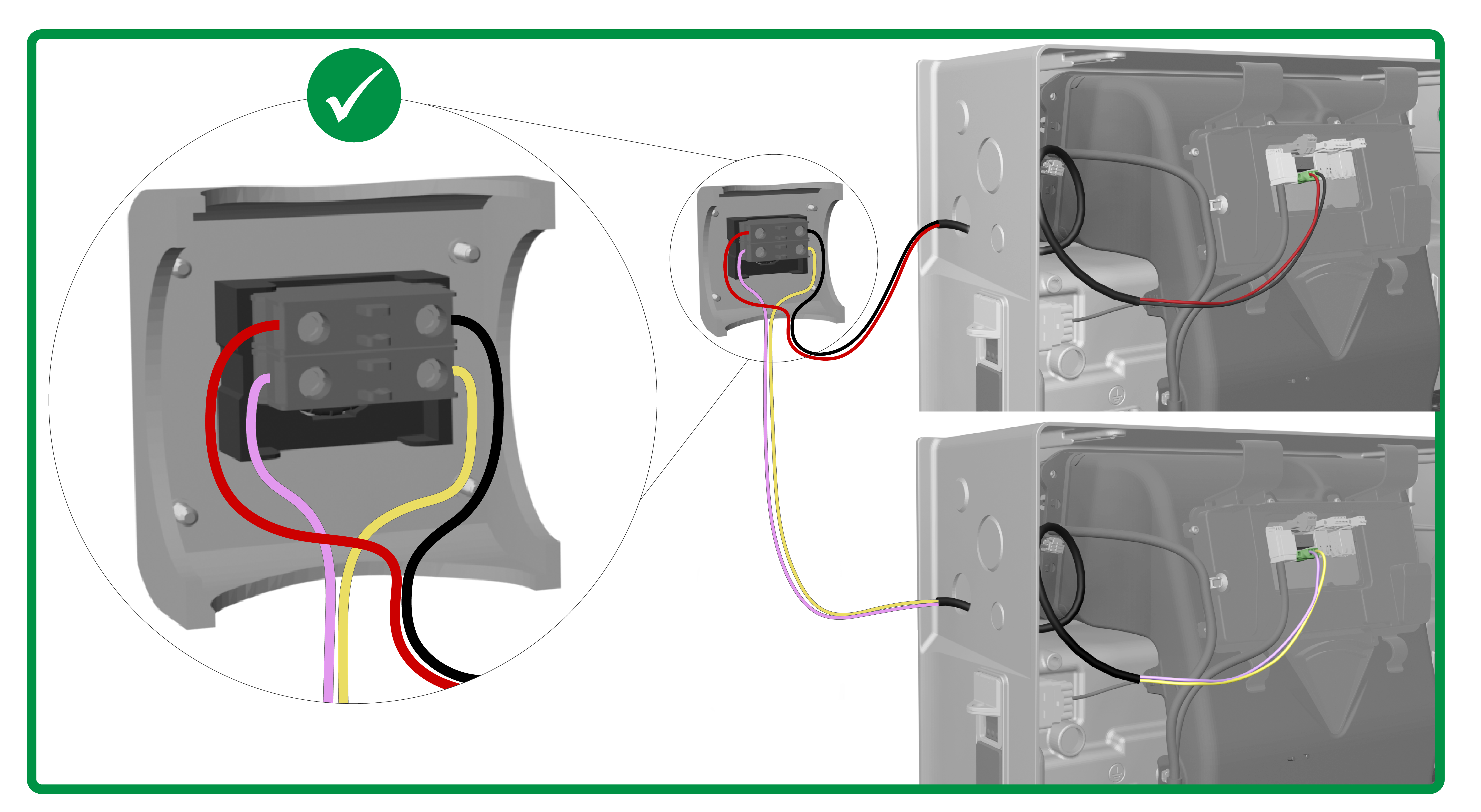
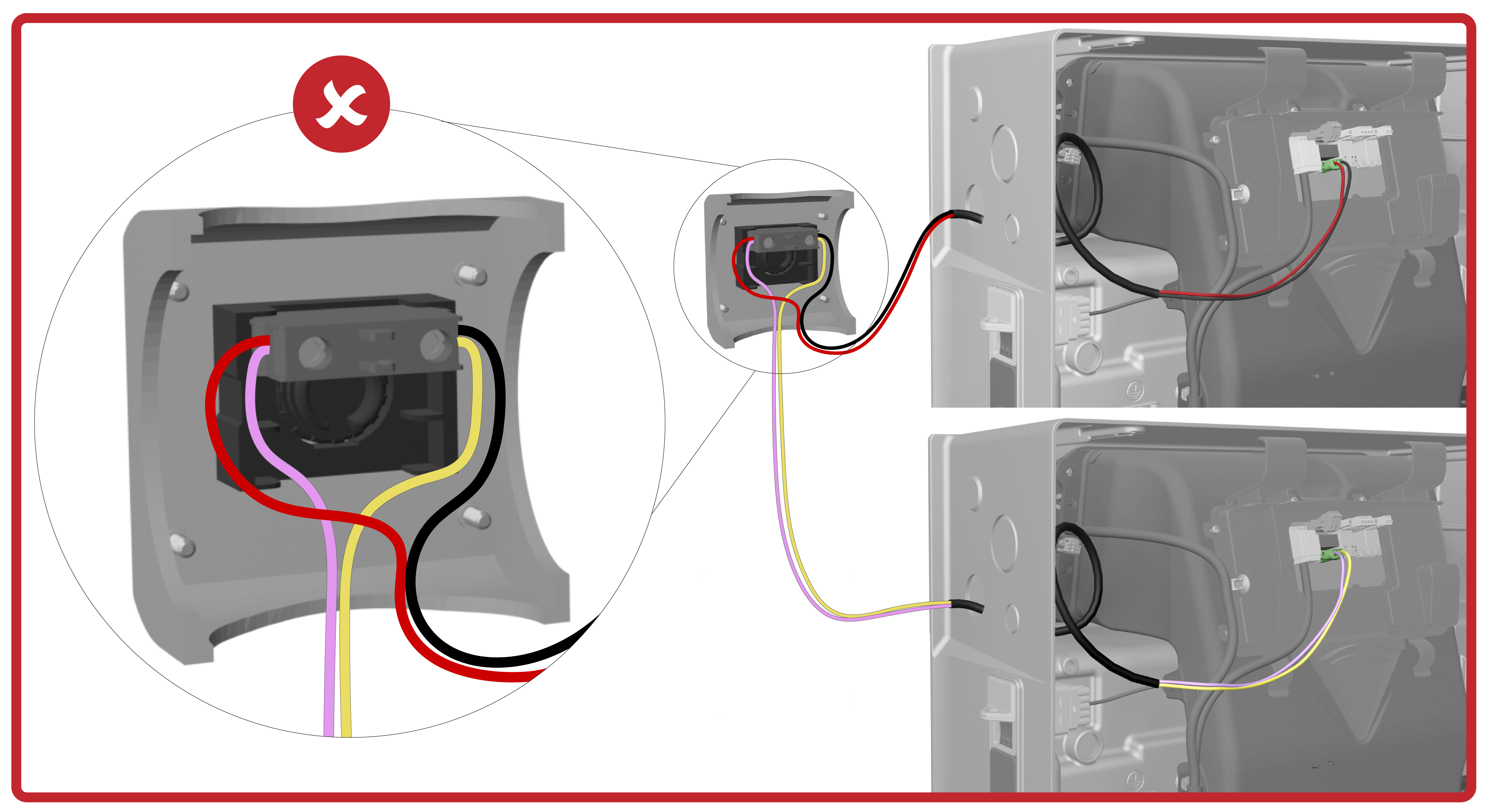
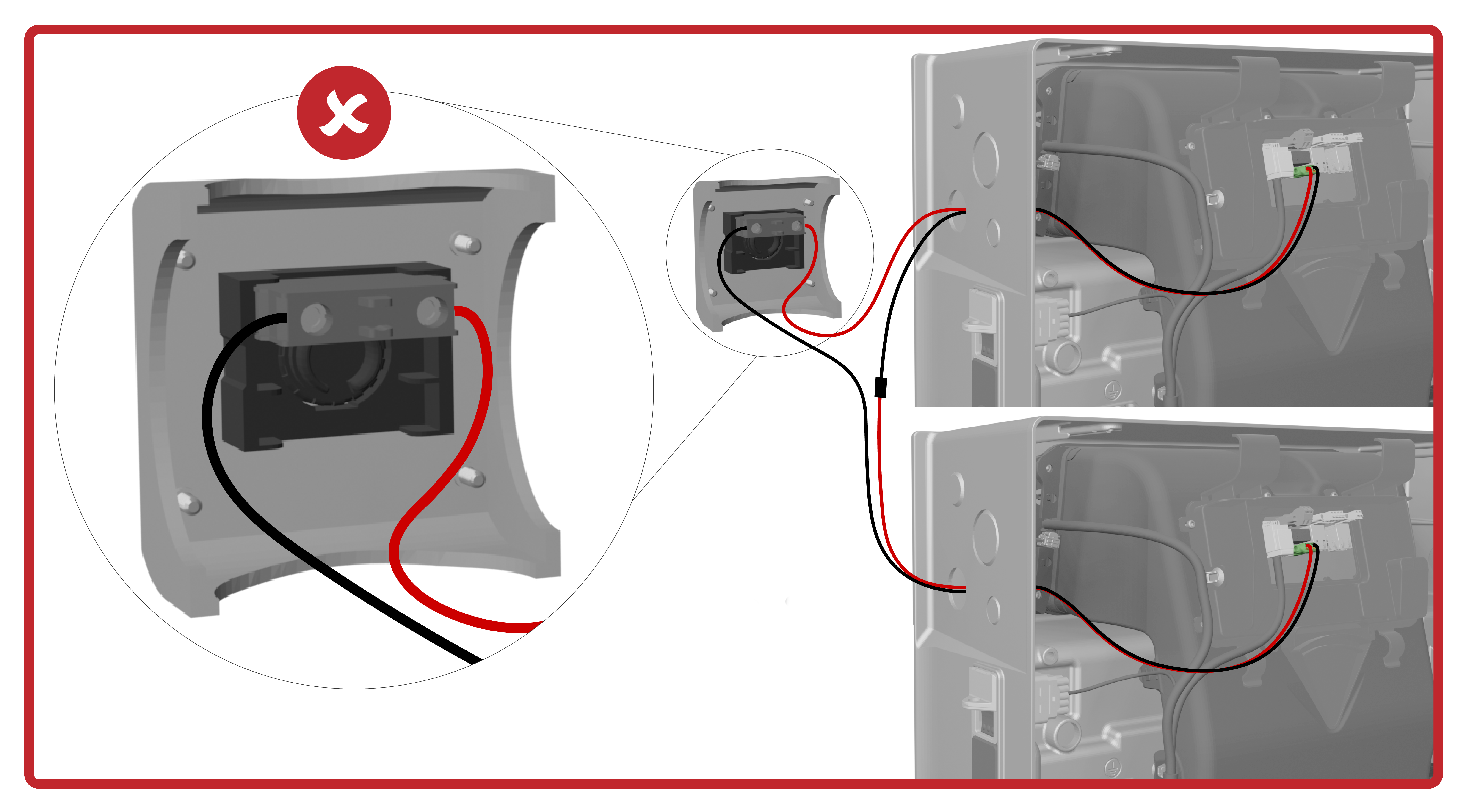
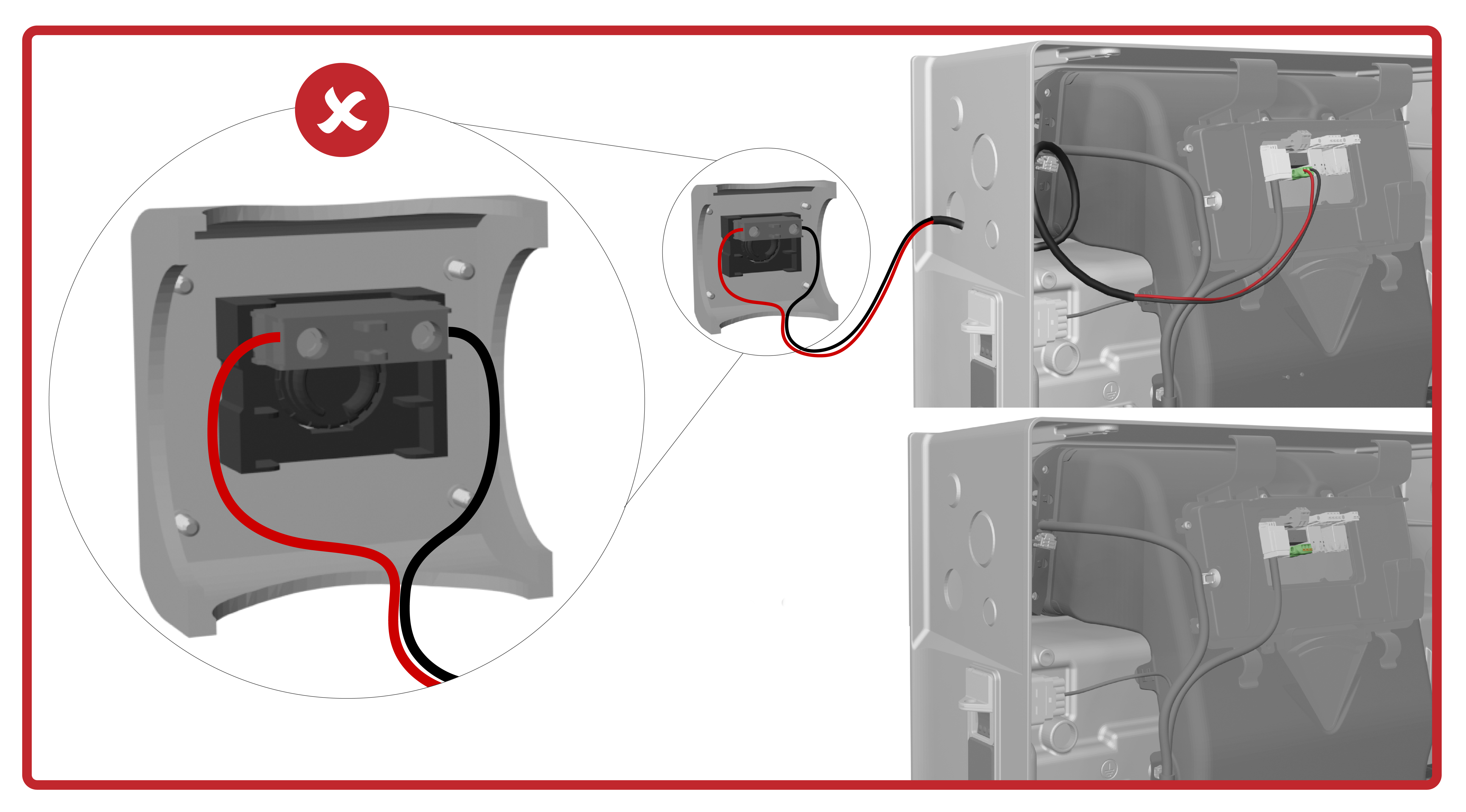
Where a System Shutdown Switch is required, connect eachPowerwall 3 to a dedicated electrical contact of the switch. Ensure the installed System Shutdown Switch has enough electrical contacts for the number of units installed.


Connecting Powerwall 3 Units via Ethernet
All Powerwall 3 units must be connected via Ethernet. The units can be connected in any order, so long as each unit is connected to at least one other unit.
Commissioning Multi-Powerwall 3 Systems
For instructions to commission a multi-Powerwall 3 system, as well as for troubleshooting steps for common issues, see the Powerwall 3 Device Setup Guide.