Appendix G: Installations with Multiple Powerwall 3 Units
| Maximum Number of Powerwall 3 Units | Up to (4X)Powerwall 3 units Note The maximum number of Powerwall 3 units per
installation may vary by market. |
| Overcurrent Protection Devices | Each Powerwall 3 requires its own circuit breaker. |
| AC Line Filter | Each Powerwall 3 requires its own AC Line Filter (see STEP 5: Install AC Line Filter for installation instructions). |
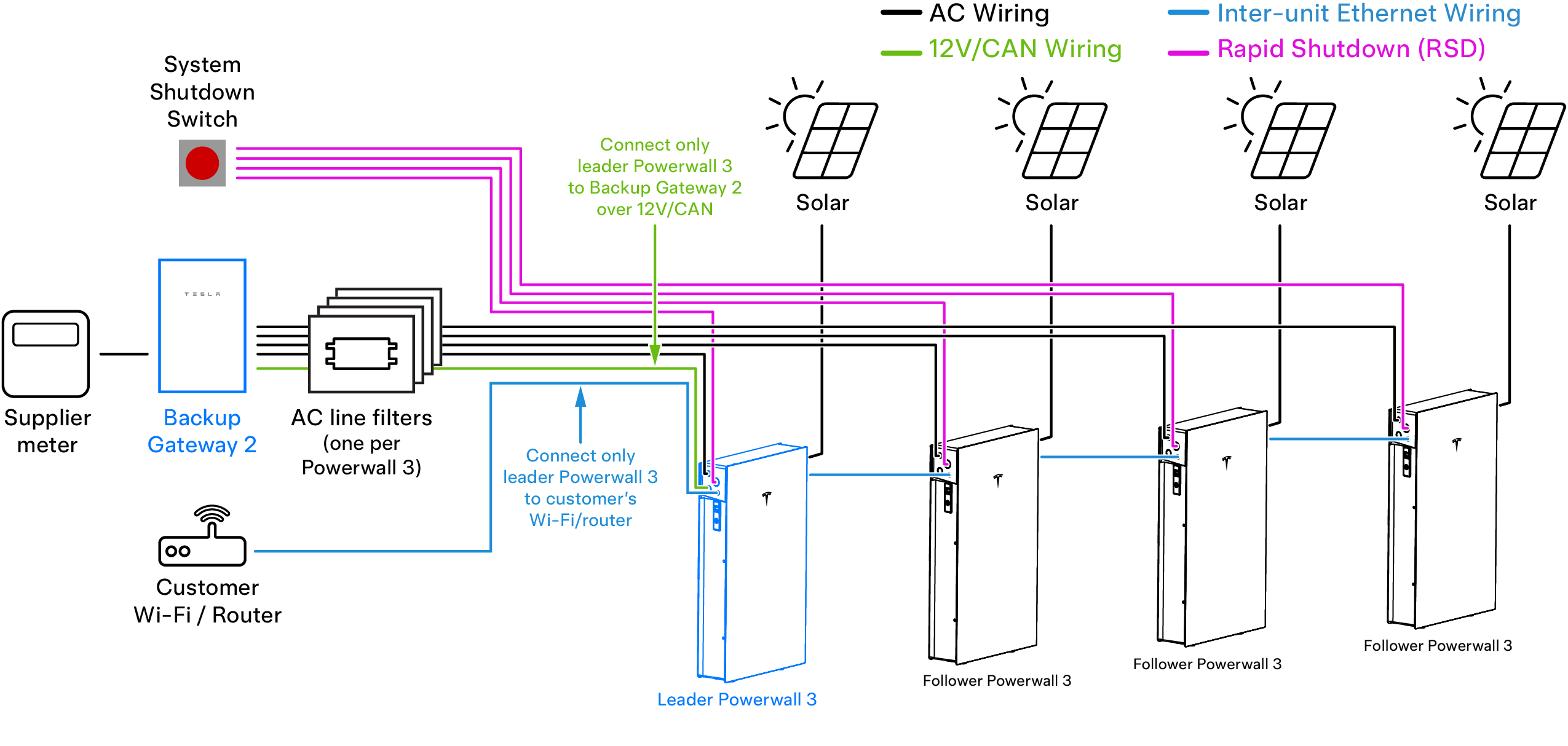
| Site Leader | The Powerwall 3 connected to the
Backup Gateway
2 over 12V/CAN wiring
is designated as the Leader Powerwall 3 unit. Note The system is
commissioned by connecting to the Leader Powerwall 3
unit. |
| Follower Unit | Any Powerwall 3 other than the Leader is connected via inter-Powerwall Ethernet wiring and is designated as a Follower unit. |
| Leader to Follower Communication | Ethernet (see Prepare Ethernet Wiring with RJ45 Connectors) |
| Internet Connection for Multiple Units | Option 1: The Leader Powerwall 3 is connected to customer router over Wi-Fi. |
|
Option 2:
Either the first or last Powerwall 3 (can be Leader or
Follower) in the chain is connected to customer router via
Ethernet. Note Only
connect the router to a Powerwall 3 at either end
of the chain; do not connect it in the middle of the chain (see
Connecting Powerwall 3 Units via Ethernet for example diagrams). |
|
| Allowable Mounting Configuration | Side-by-side (front-to-back stacking is not supported for multiple Powerwall 3 units) |
| Maximum Wire Length Between Units | See Plan Cable Length Between Components |
| Splitting PV Production Between Multiple Units | Split PV production (strings) equally between the Powerwall 3 units. |
| System Shutdown Switch with Multiple Units | Where a single System Shutdown Switch is required, each unit must be wired to a dedicated switching pole of the switch. Ensure the installed System Shutdown Switch has enough switching poles for the number of units installed. See Appendix E: (Optional) Install System Shutdown Switch for switch requirements and additional information. |
Optional System Shutdown Switch with Multiple Powerwall 3 Units
Where a System Shutdown Switch is installed, each Powerwall 3 must be wired to a dedicated switching pole of the switch. Ensure the installed System Shutdown Switch has enough switching poles for the number of units installed.

In the event multiple System Shutdown Switches are required to accommodate the number of Powerwall 3 units installed, simply install multiple switches, placing them physically near each other and following all local codes and requirements.

Connecting Powerwall 3 Units via Ethernet
All Powerwall 3 units must be connected via Ethernet. The units can be connected in any order, so long as each unit is connected to at least one other unit.


Commissioning Multi-Powerwall 3 Systems
For instructions to commission a multi-Powerwall 3 system, see the Powerwall 3 Commissioning Guide.