STEP 5: Install AC Line Filter
AC Line Filter Overview
| 1 | Mounting feet for wall mounting (Must be field mounted to the enclosure) |
| 2 | Enclosure |
| 3 | AC Line Filter |
| 4 | Protective Earth terminal stud (M6) on the enclosure |
| 5 | Protective Earth terminal stud (M6) on the enclosure door |
| 6 | Protective Earth jumper from enclosure to the enclosure door |
Mounting Location
The AC Line Filter enclosure is IP65-rated and can be mounted on a wall in any orientation, indoors or outdoors. The AC Line Filter must be installed on the Powerwall 3 AC circuit; between the Powerwall 3 breaker (i.e., mounted on the DIN rail inside the Backup Gateway 2) and the Powerwall 3 unit.
See Appendix C: System Wiring Diagrams for the detailed wiring diagram.
Mount the Enclosure
- Using a metal hole saw, drill out cable
access holes from the enclosure. The hole can be drilled on any side of the enclosure and
the size can be either M20, M25, M32, or M40 depending on the knockout you punch out on
the Powerwall 3.
Figure 2. Enclosure with Cable Access Hole Options 
- Refer to the mounting feet assembly
instructions document provided in the AC Line Filter box and mount the mounting feet to
the enclosure.NoteThe mounting feet hardware must be assembled in the order prescribed in the document and torqued to 2.3 Nm to ensure a watertight seal.
Figure 3. Enclosure with Mounting Feet Installed 
- Using a drill and level, mount the
enclosure to a wall.
Figure 4. Enclosure Dimensions and Mounting Holes 
Make AC Power Connections
Warning
Before making the AC
power connections, ensure that the AC circuit breaker of the main service disconnect is
OFF and secured against reconnection.
- (Conduit installations only) Run conduit as needed and attach the conduit fitting to the AC Line Filter enclosure.
- Run the AC Line, Neutral, and the Protective Earth conductors from the Backup Gateway 2 and Powerwall 3 through the conduit or cable gland into the AC Line Filter enclosure.
- Create a water drip loop inside the AC
Line Filter enclosure with extra wiring.NoteThe water drip loop is to prevent water from entering the wiring terminals if water enters into the enclosure through the cable glands.
- Clear out any debris that may be present in the enclosure.
- Connect the Protective Earth conductor to
the enclosure:CAUTIONDo not connect bare wires. Use M6 ring terminals.
- Strip the conductor insulation to a
length recommended by the ring terminal manufacturer.
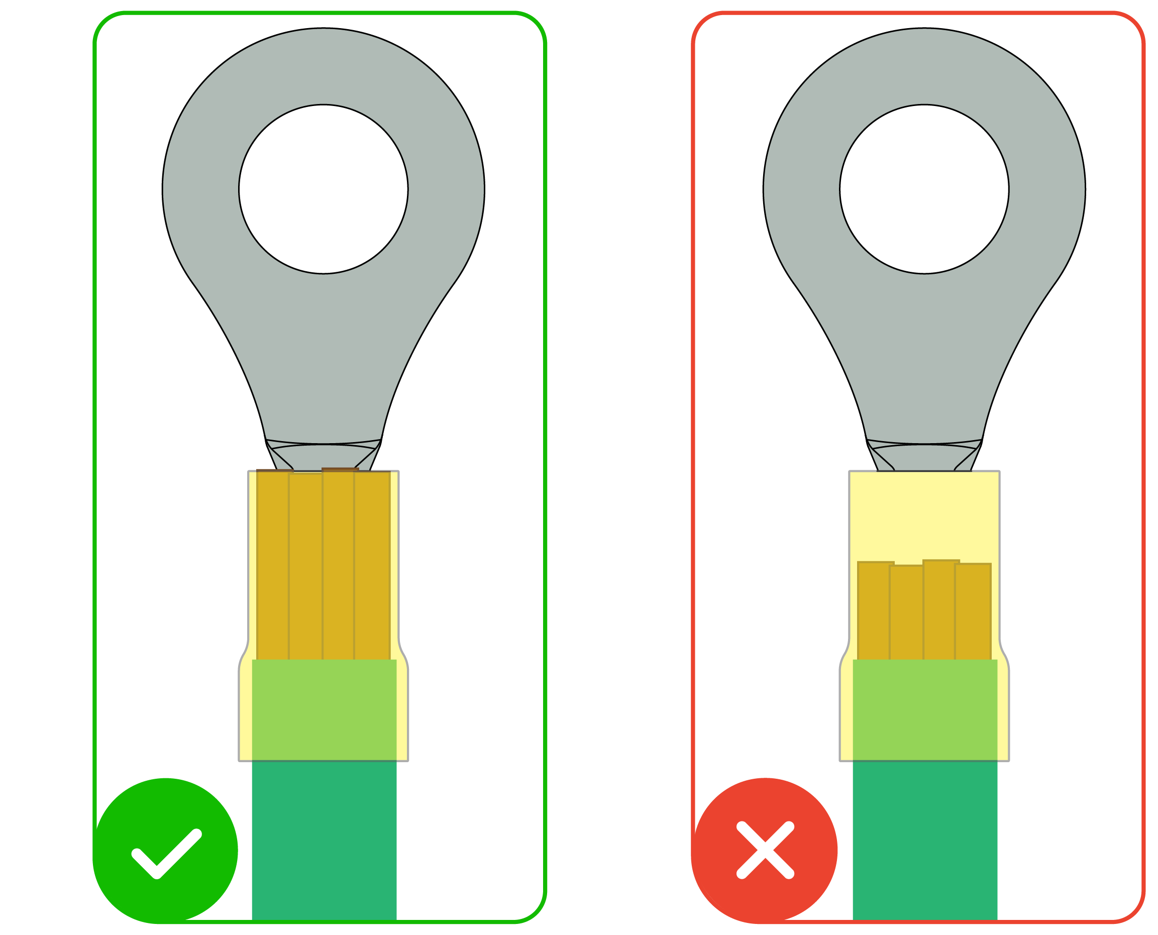
- Using a crimping tool, crimp the ring
terminal onto the end of the conductor.NoteEnsure the ends of the copper strands are visible at the bottom of the ring terminal, indicating the conductor is making strong contact with the ring terminal.
- Insert the ring terminal onto the Protective Earth stud; using a 7/16 in (10 mm) socket wrench (see Required Tools), tighten the fastener to 4 Nm.
- Strip the conductor insulation to a
length recommended by the ring terminal manufacturer.
- Similarly, repeat Step 5 to connect the Protective Earth conductor from Powerwall 3 to the enclosure, and then from enclosure to the enclosure door.
- For the AC Line
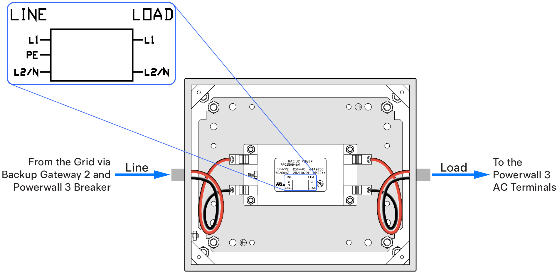
and Neutral conductors:NoteThe AC Line Filter has Line and Load terminals. Ensure to:
- Connect the AC Line and Neutral conductors from the Grid via Backup Gateway 2 and Powerwall 3 breaker to the AC Line Filter's Line terminals.
- Connect the AC Line and Neutral conductors from the Powerwall 3 AC terminals to the AC Line Filter's Load terminals.
 NoteSee Appendix C: System Wiring Diagrams for the detailed wiring diagrams.
- Strip the conductor insulation up to 17 mm.
- Insert the conductor as far as possible into the terminal; using a Pozidriv #2 screwdriver or bit (see Required Tools), tighten the screw to 2.3 Nm.
- Perform a pull test to ensure the conductor is fully seated in the terminal. Push the conductor back in after the pull test.
- After connecting the conductors, gather them and secure them with a cable tie.
- Install the enclosure door and tighten
the door screws.
Figure 5. Enclosure with Door Installed