Design Considerations
Supported Configurations
- Up to (4) Powerwall 3 units with up to (3) Powerwall 3 Expansion units
can be installed with Backup Switch, Backup Gateway 2, or Gateway 3NoteBackup Switch is not certified for installation in Canada; only install Powerwall 3 with Backup Gateway 2 or Gateway 3 in Canada.NoteThird party MLPE solutions, such as optimizers, are not compatible with Powerwall 3.
- Powerwall 3 AC-coupled solar (Tesla Solar Inverter or third party solar inverters)
-
Powerwall 3 is not yet compatible with the following:
- Neurio remote energy meters (all metering must be performed by Backup Switch, Backup Gateway 2, Gateway 3, and/or Tesla Remote Energy Meter; see Metering Considerations for more information)
- Other batteries (Powerwall 2, Powerwall+, or third party batteries)
- Non-backup systems
Powerwall 3 Solar
Powerwall 3 has an integrated inverter and 6 MPPTs, with a maximum solar input of 20 kW DC.
Warning
It is critical
that MCIs are installed on any PV system connected to Powerwall 3. MCI(s) are required for each
PV string connected to Powerwall 3, even on systems where Rapid Shutdown
(RSD) requirements do not apply. See the Powerwall 3
installation manual for more information.
Warning
Where it is
allowable to install only (1) MCI per string, MCI-1 must be used. See
the Powerwall 3
installation manual for more information.
Note
See AC-Coupled Solar System Sizing for
information about sizing AC-coupled solar (Tesla Solar Inverter or third party solar
inverters) with Powerwall 3.
System Tie-in
- Only Tesla devices are compatible
with Powerwall; no third-party equipment in lieu of Backup Switch, Backup Gateway
2, or Gateway 3.NotePowerwall 3 systems must have a grid connection. Fully off-grid systems are not supported.NoteWhen using Eaton branch breakers on continuous loads such as Powerwall, Eaton strongly recommends using only type BR breakers that end in H (for instance BR260H).
- Up to 200 A service with Form 2S meter socket when designing with Backup Switch.
- Backup systems must be 120/240 V single/split-phase service only.
- Backup Gateway / Gateway 3 should be installed with either a 200 A or smaller service or (in absence of a service rating) maximum 200 A of loads downstream of Backup Gateway 2 / Gateway 3 per NEC load calculations.
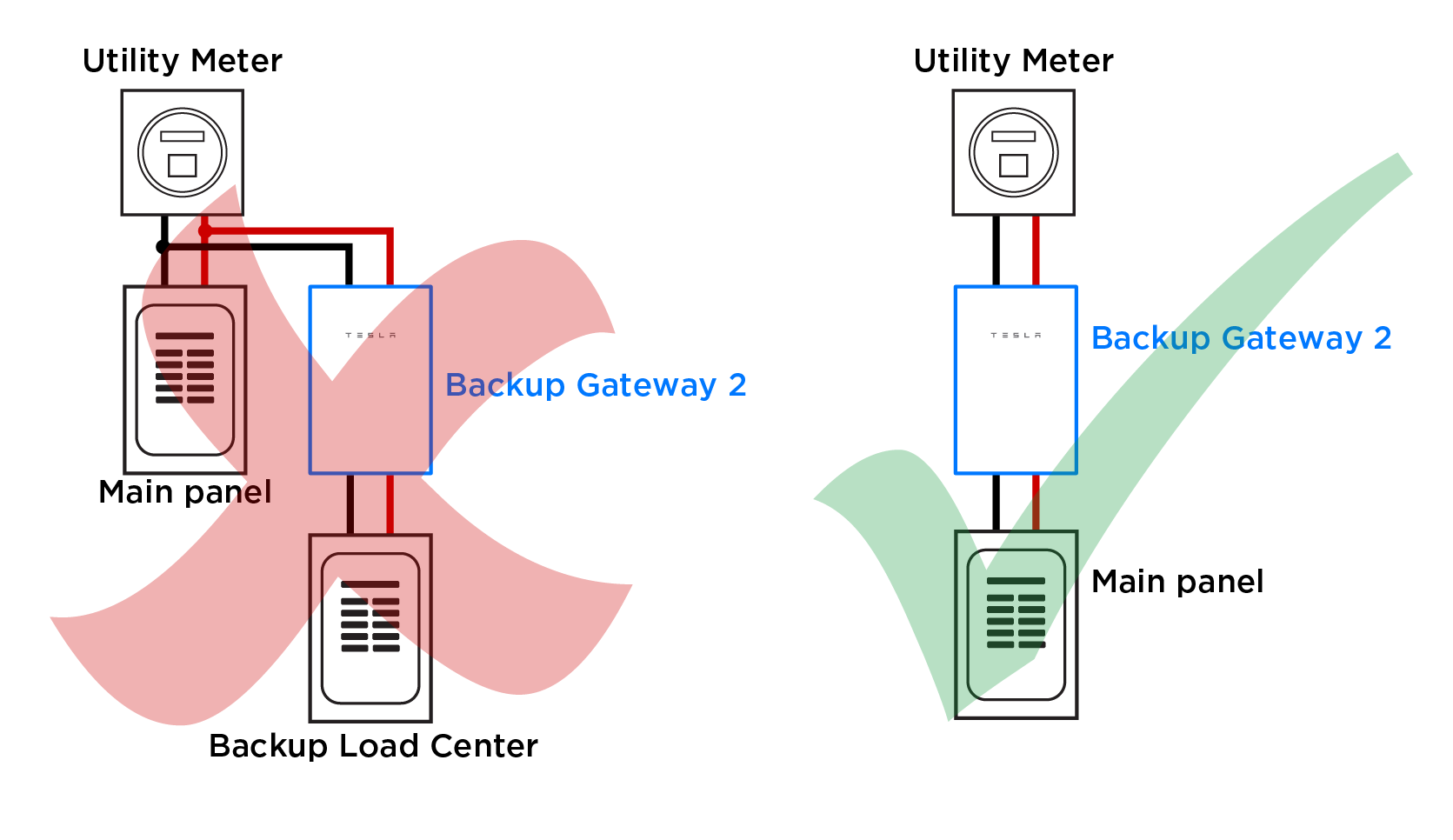
- No line-side or load-side taps
for Backup Gateway 2 /
Gateway 3 interconnection:
- Line Side Tap: Connecting
the Backup Gateway 2
/ Gateway 3 to the line side of the main panel or service
disconnect by tapping existing wiring is never allowed, according to NEC
230.82. Inherently, there are always loads downstream of the Backup Gateway 2 /
Gateway 3; it is not permissible to interconnect loads to the
supply side of the service disconnect (left figure). It is permissible
for the Backup
Gateway 2 / Gateway 3 to intercept the service feeders (right
figure) because the main breaker in the Backup Gateway 2 /
Gateway 3 becomes the main service disconnect.
- Load Side Tap: Connecting
the Backup Gateway 2
/ Gateway 3 to the load side of the main panel or service
disconnect by tapping via insulation-piercing connectors is non-standard
practice and increases the possibility of issues and/or failed
inspections. Connection to the Backup Gateway 2 /
Gateway 3 must be a directly routed feed.
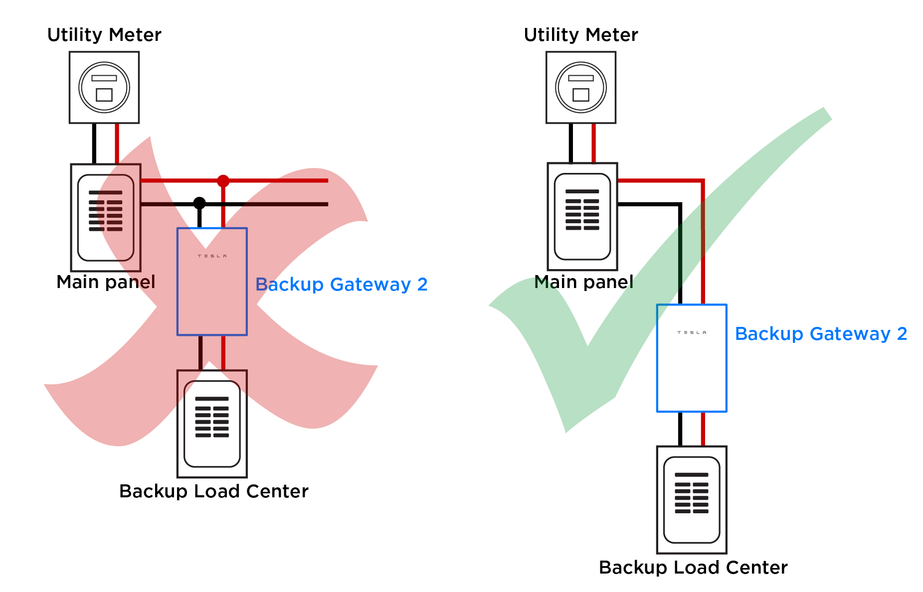
NoteWhen using the Backup Switch as the site relay, it is permissible to interconnect the generation panel via a tap because there are no loads downstream of the generation-only panel.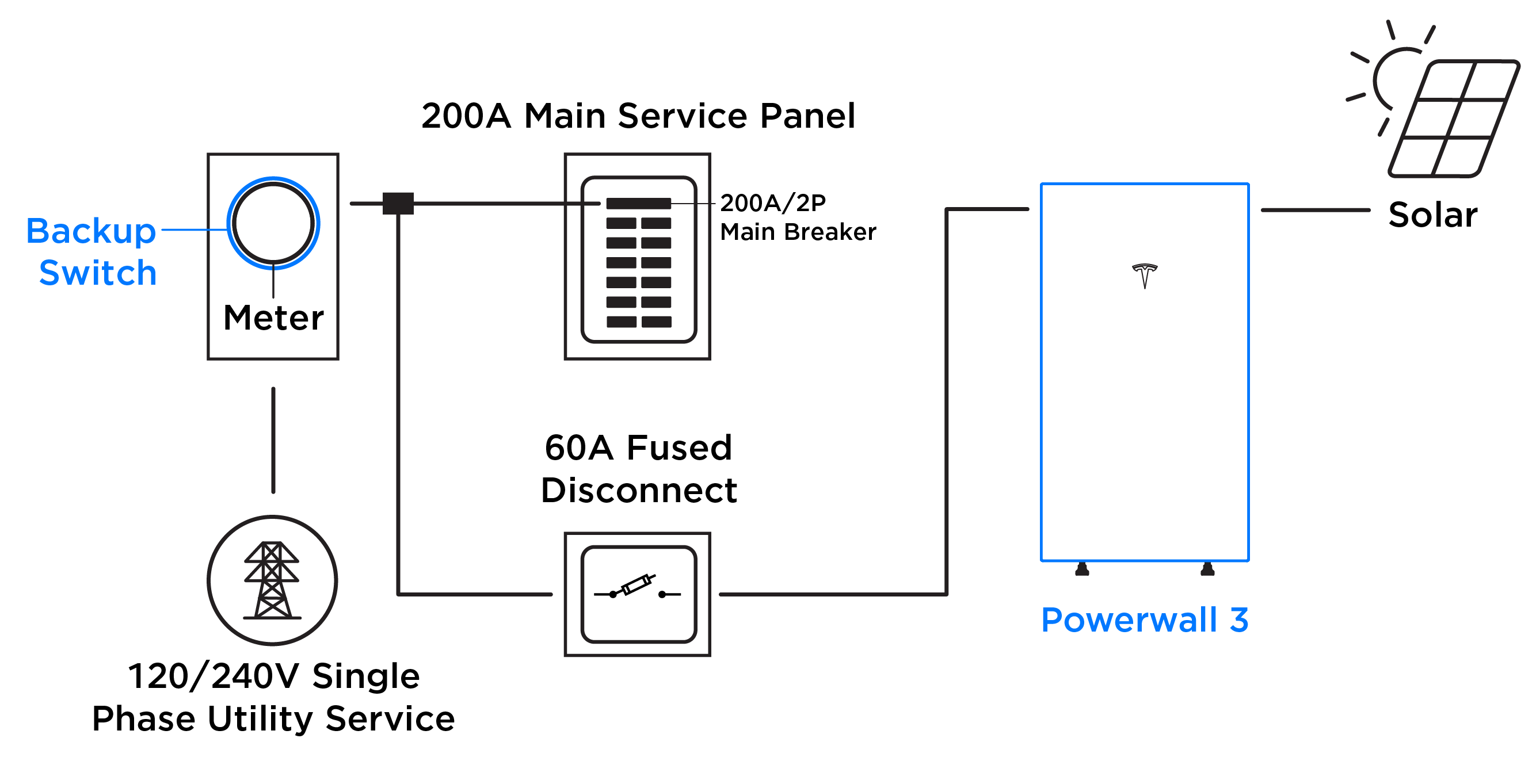
- Line Side Tap: Connecting
the Backup Gateway 2
/ Gateway 3 to the line side of the main panel or service
disconnect by tapping existing wiring is never allowed, according to NEC
230.82. Inherently, there are always loads downstream of the Backup Gateway 2 /
Gateway 3; it is not permissible to interconnect loads to the
supply side of the service disconnect (left figure). It is permissible
for the Backup
Gateway 2 / Gateway 3 to intercept the service feeders (right
figure) because the main breaker in the Backup Gateway 2 /
Gateway 3 becomes the main service disconnect.
- Powerwall must not interact with (or must be completely isolated from) any other storage systems or generation sources not listed to UL 1741.
- An overcurrent protection device
(OCPD) is always utilized for Powerwall 3 tie in
(705.12).
- The default required OCPD
is 60 A; Powerwall 3 can be configured
with a maximum current / power output, in which case one of the
following breaker sizes is required
Table 1. Maximum Continuous Current Options Maximum Continuous Current Output (AC) Breaker (Overcurrent Protection) 48 A On-grid
64 A Off-grid*11.5 kW On-grid
15.4 kW Off-grid80* 48 A 11.5 kW (default) 60 A 41.7 A 10 kW 60 A 31.7 A 7.6 kW 40 A 24 A 5.8 kW 30 A *15.4kW off-grid maximum continuous discharge power is only available if on-grid rating is 11.5 kW. If enabled, Powerwall 3 must be installed with an 80 A breaker and appropriately sized conductors. Powerwall 3 can only provide 15.4 kW when off-grid and when there is sufficient solar.
CAUTIONIf using a fuse as the Powerwall 3 overcurrent protection device, it must be a Class RK1 Fast Acting fuse. Use one of the following fuses or equivalent:Fuse Type Manufacturer Part Number 80 A Fast-Acting Fuse, Class RK1, >= 250VAC, CLF Littelfuse KLNR080 Eaton / Bussmann KTN-R-80 Mersen / Ferraz Shawmut A2K80R 60 A Fast-Acting Fuse, Class RK1, >= 250VAC, CLF Littelfuse KLNR060 Eaton / Bussmann KTN-R-60 Mersen / Ferraz Shawmut A2K60R 40 A Fast-Acting Fuse, Class RK1, >= 250VAC, CLF Littelfuse KLNR040 Eaton / Bussmann KTN-R-40 Mersen / Ferraz Shawmut A2K40R 30 A Fast-Acting Fuse, Class RK1, >= 250VAC, CLF Littelfuse KLNR030 Eaton / Bussmann KTN-R-30 Mersen / Ferraz Shawmut A2K30R - The default required OCPD
is 60 A; Powerwall 3 can be configured
with a maximum current / power output, in which case one of the
following breaker sizes is required
- Controlled sources such as Powerwall 3 can avoid the supply rules
of NEC 705.12, including the 120% rule, when panel limits are used and backfeed
is limited using software (also known as a Power Control System (705.13)), so no
backfeed calculation is required. See Power Control System
(PCS) Features for Powerwall Systems for more information.CAUTIONFor systems with Powershare-capable vehicles and EV chargers in the backup circuit, the Tesla-branded EV charger must be considered a generation source in backfeed calculations. See the Powershare Home Backup Installation Manual for more information.
- Recommend that total Powerwall supply is able to power the single largest automatic load in the backup circuit (see Backup Loads Supported per Powerwall Quantity).
- Any/all backup load centers abide by 705.12 or 705.13 and are adequately protected with an overcurrent protection device.
- A load center with generation and any others upstream must abide by 705.12 or 705.13.
- Site and solar monitoring must be installed to capture overall power flow to/from the site, as well as all solar production.
- Powerwall, Backup Gateway, and Backup
Switch are rated for 10 kA of fault current. If potential fault current
onsite is greater than 10 kA:
- A J-class fuse upstream of the Backup Gateway 2 can be utilized to make the Backup Gateway 2 rated for 22 kA.
- Backup Switch is rated for 22 kA when a minimum 22 kA main breaker is used in conjunction with the Backup Switch.
- Gateway 3 is rated for 25 kA of fault current when installed with an Eaton CSR or BWH main breaker, or 22 kA when installed with a Square D QO main breaker.
- Multiple Backup Gateways can be installed on a single site to accommodate sites with greater than 200A service equipment; see the Multiple Backup Gateways on a Single Site Application Note on Partner Portal.
Equipment Location
Powerwall is not installed in habitable locations.