Powerwall 3 DC System Sizing
-
Powerwall 3 can be
configured as up to a 11.5 kW / 48 A AC rated inverter that can
support up to a maximum DC system size of 20 kW.
- 20 kW DC is the absolute maximum solar system size that Powerwall 3 can support.
- Powerwall 3 has a boosting
feature that can send 5 kW of DC power continuously from solar to the
battery at the same time that up to 11.5 kW / 48 A of solar is
inverted to AC power, leading to a potential total DC power of 16.5 kW. This helps alleviate clipping concerns and enables sizing the DC
system larger, but only if the battery is being used in a way that it
will have available charge power during the peak solar production hours
of the day.NoteWhen a Powerwall 3 is installed with Expansion unit(s), the boosting feature can send 8 kW of DC power continuously from solar to the battery, leading to a potential total DC power of 19.5 kW, of which 11.5 kW / 48 A is inverted to AC power. Adding the Expansion unit(s) will further alleviate clipping concerns and enables sizing the DC system larger.
- If Powerwall 3 is power / current limited, a larger DC solar system size may experience curtailment. Size the DC solar system appropriately based on the configured power / current output.
- Where clipping may occur, the amount of clipping depends on the specific scenario.
- Each Powerwall 3 has (6) MPPTs available for Solar. When strings are combined on the roof, the following MPPTs can be jumped to
double the total PV input current capacity to 26A:
- MPPT 1 to MPPT 2
- MPPT 5 to MPPT 6
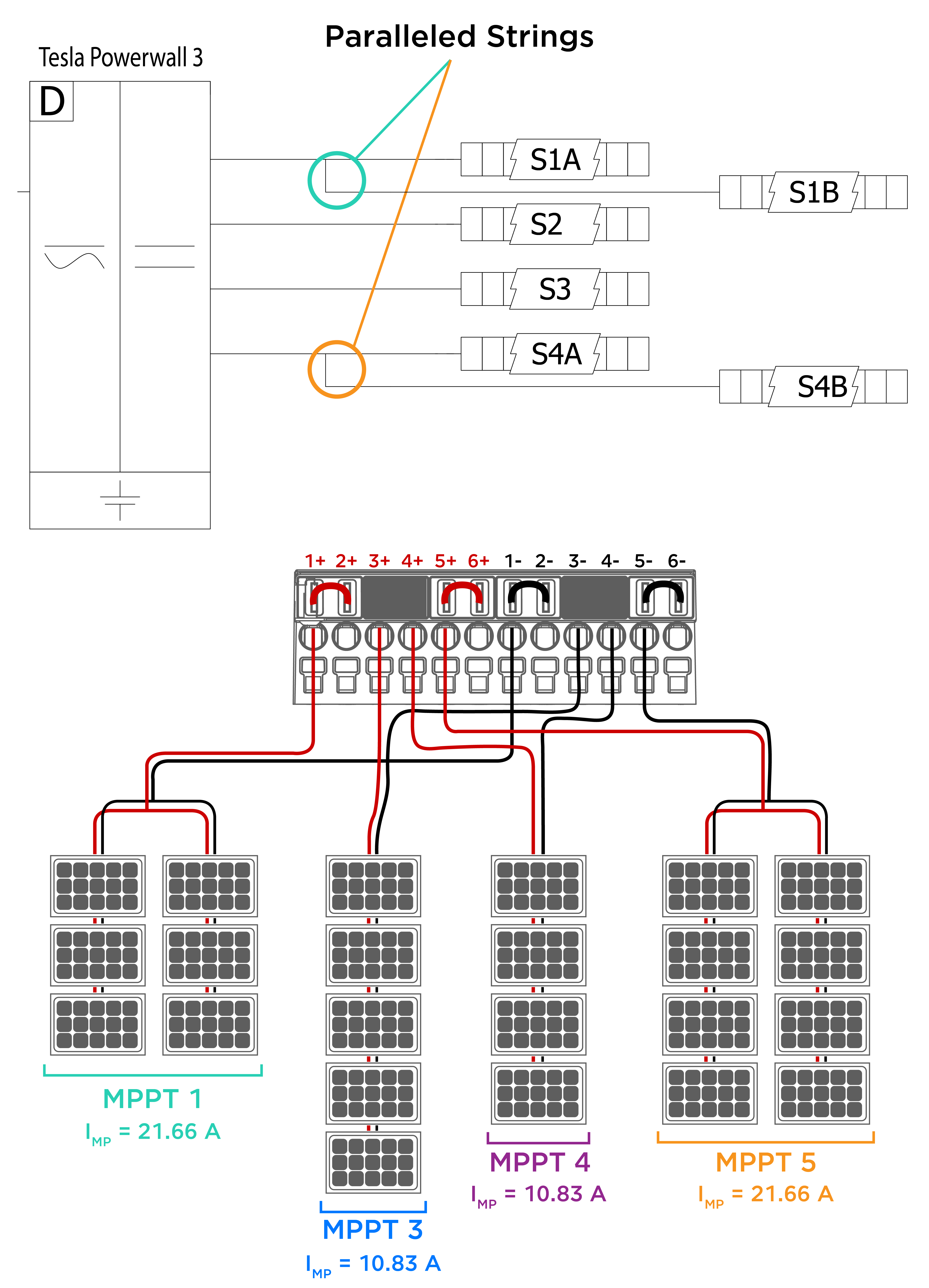
NoteMPPT inputs 3 and 4 cannot be jumped and are closed from the factory.NoteWhen the Powerwall 3 product label lists 15 A IMP, jumpers can be used to parallel MPPT to double the total PV input current capacity to 30 A.NoteFor Solar Roof and older PV modules with IMP < 6.5A, the jumper is not required.NoteIf there are more than three PV strings, strings can be combined upstream of Powerwall 3 so long as the voltage and current ratings of the system do not exceed the capabilities of Powerwall 3.Figure 1. Powerwall 3 with Solar Panels Stringing Example:  NoteIn the example above, the strings connected to MPPTs 1 and 5 are combined on the roof, so jumpers are required.
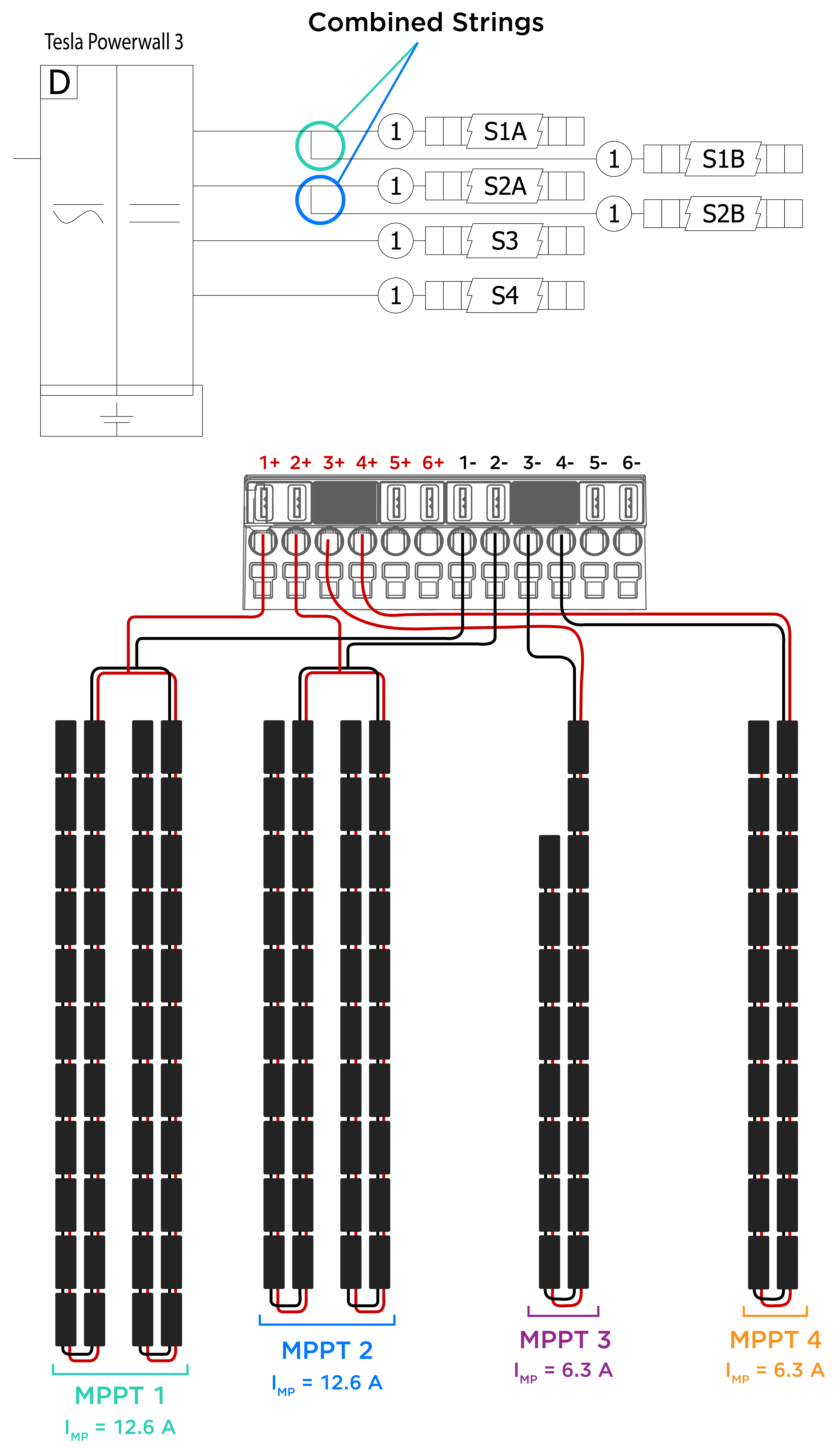
Figure 2. Powerwall 3 with Solar Roof Stringing Example: 
- When
calculating the minimum and maximum number of modules per string, use the web version or desktop version (downloads to your system) of the
Tesla Solar Stringing Tool available on Partner Portal. For instructions on how
to use the tool, see the web version User Guide or the desktop version User Guide. Or, you can use the following variables
and equation:
- A = VOC at standard test conditions (STC) for the modules
- B = Voltage temperature coefficient
- C = Number of modules in string
- A * B * C = X
- 60 ≤ X ≤ 550V
- Total DC circuit distance, from +
MPPT terminal to - MPPT terminal (including module wire leads, jumper wires and
all wiring within the array boundary for any individual string), shall not
exceed 160 m (525 ft) for single
strings or paralleled strings
- Total DC circuit distance refers to the entire round trip wire distance, from inverter to the roof, then back to the inverter
- Ensure paralleled strings are the same distance, or as close to the same distance as possible (if the paralleled strings are different distances, it is likely the MCIs will not function properly; this likelihood increases the greater the difference in paralleled string distances)
-
Powerwall
3 is a string inverter. Individual strings should not be extended over
mounting planes with different pitches and/or azimuths to provide peak
performance of the system. Series strings must have modules on the same pitch
& azimuth, and strings of equal distance can be combined in parallel.
- Note that a situation where all 20 kW are simultaneously producing at peak may result in solar clipping. Tesla recommends, but does not require, diversifying azimuths when the array is significantly oversized. The (6) MPPTs are particularly suited for sites where the strings may not be on the same azimuth and are therefore not producing at peak simultaneously.
- If installing multiple Powerwall 3 units, it is recommended but not required to distribute the DC PV system across all Powerwall 3 units so that each Powerwall 3 receives the benefits of DC coupling solar
Available Third-Party Solar Design Tools
Powerwall 3 has been added to the following solar design tool databases:
- Aurora
- Sunobi