Appendix A: Powerwall+ and Powerwall 3 Permanent Non-Export
Overview
Where required by utilities, Powerwall+ and Powerwall 3 can be placed in a permanent non-export mode. This means that in the following scenarios, Powerwall+ / Powerwall 3 will curtail solar to prevent power from being exported back to the grid:
- The battery is fully charged and more solar is being produced than the system is consuming
- Solar is being produced at a higher rate than the battery can charge at, e.g. 7.6 kW of solar on a 5 kW battery
This feature is available beginning with Powerwall software version 22.18. One important note is that, in a Powerwall+ or Powerwall 3 system, Powerwall+ / Powerwall 3 is the only solar inverter capable of curtailing solar as described above. As such, Powerwall+ / Powerwall 3 is referred to as “controlled solar.” Third party solar inverters cannot be controlled by the Powerwall system Site Controller in the same manner and are referred to as “uncontrolled solar.”
This document describes three possible permanent non-export configurations: one with exclusively controlled solar, one with uncontrolled (third party) solar that is allowed to export solar to the grid, and one with uncontrolled (third party) solar that is not allowed to export solar to the grid.
Install Metering for a Permanent Non-Export System
Metering in a permanent non-export system is essentially the same as in any Powerwall system:
- Site metering must capture all loads and generation, including non-backup loads
- Solar metering must capture all solar generation, including third party solar inverters
In addition to the Powerwall system metering, any third party solar inverter also requires its own Site meter if it is configured for non-export. Third party Site metering should follow the third party inverter’s installation instructions and should not be modified by the Powerwall system.
The following examples illustrate some common metering configurations for a permanent non-export system.
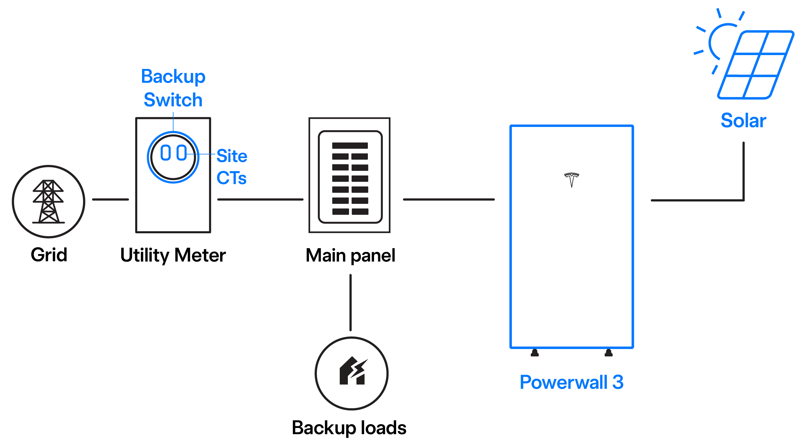
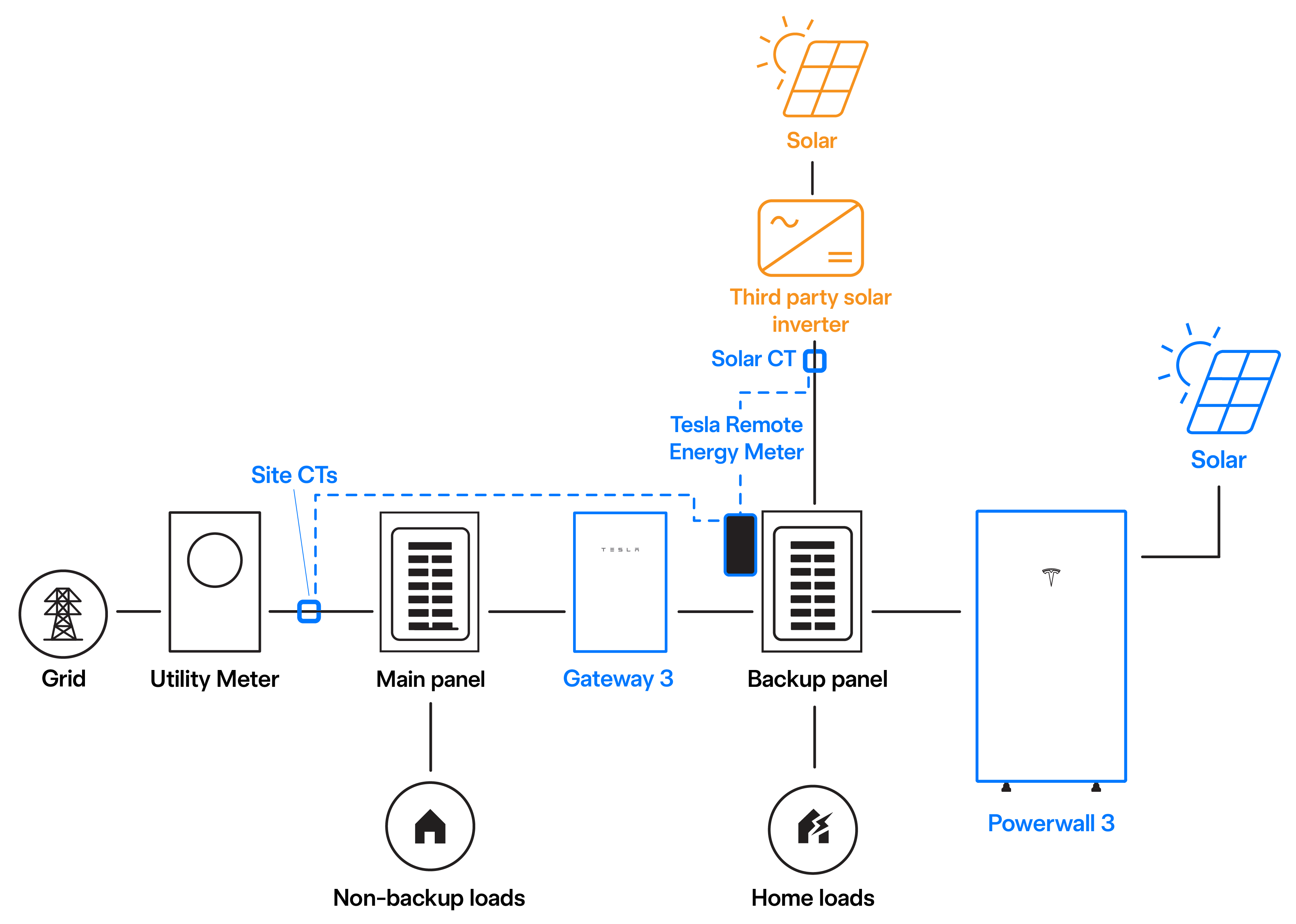
Example 1: Powerwall 3 Permanent Non-Export System with Only Controlled Solar
| Energy to be Metered | Meter | CT(s) | Meter Configuration |
|---|---|---|---|
| Site backup loads | Backup Switch (pictured in example diagram above) or Gateway 3 Meter Z | Backup Switch / Gateway 3 Meter Z | Preconfigured as Meter Z: Site |
| Powerwall 3 Solar Generation | Powerwall 3 integrated energy meter | N/A | N/A |
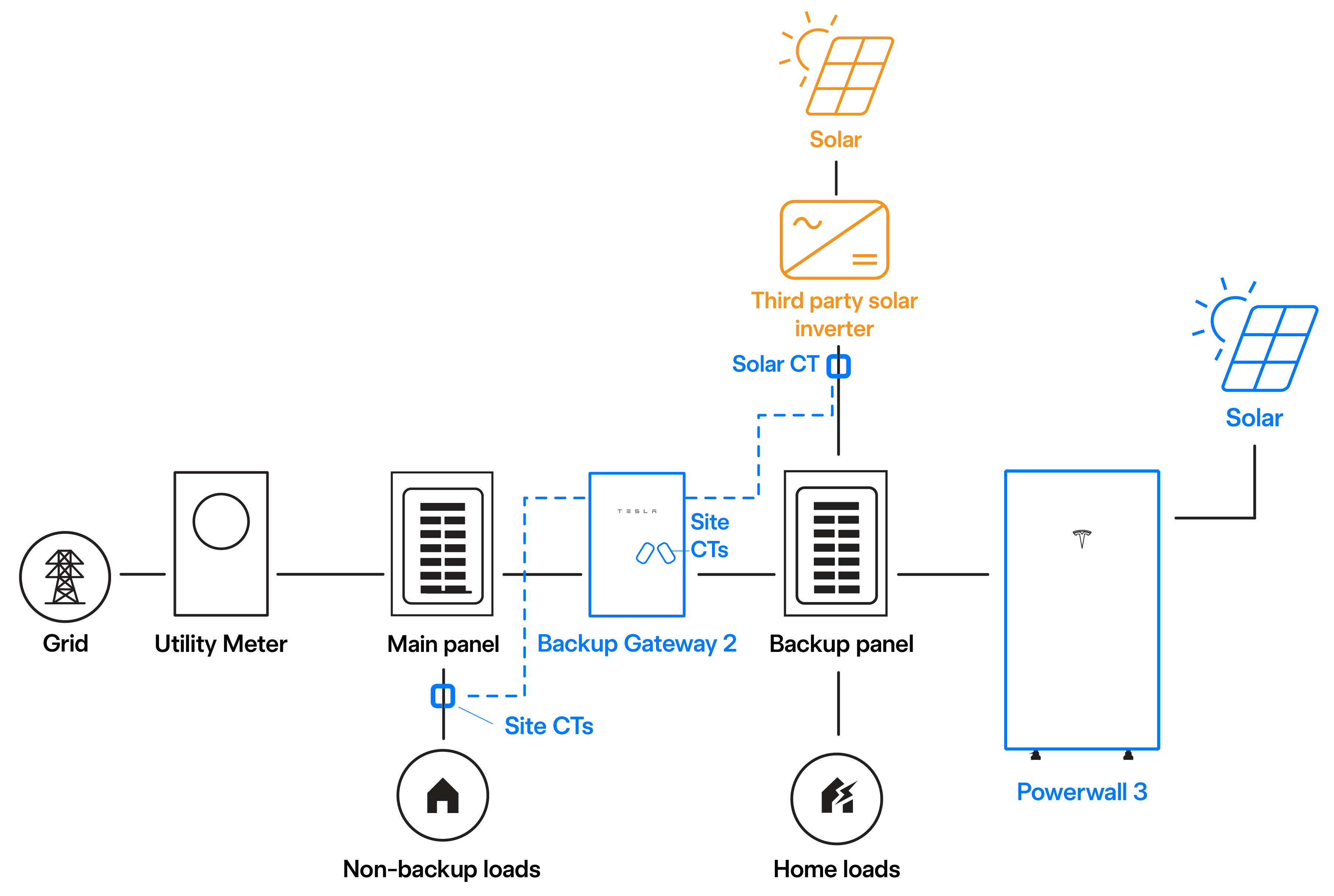
| Energy to be Metered | Meter | CT(s) | Meter Configuration |
|---|---|---|---|
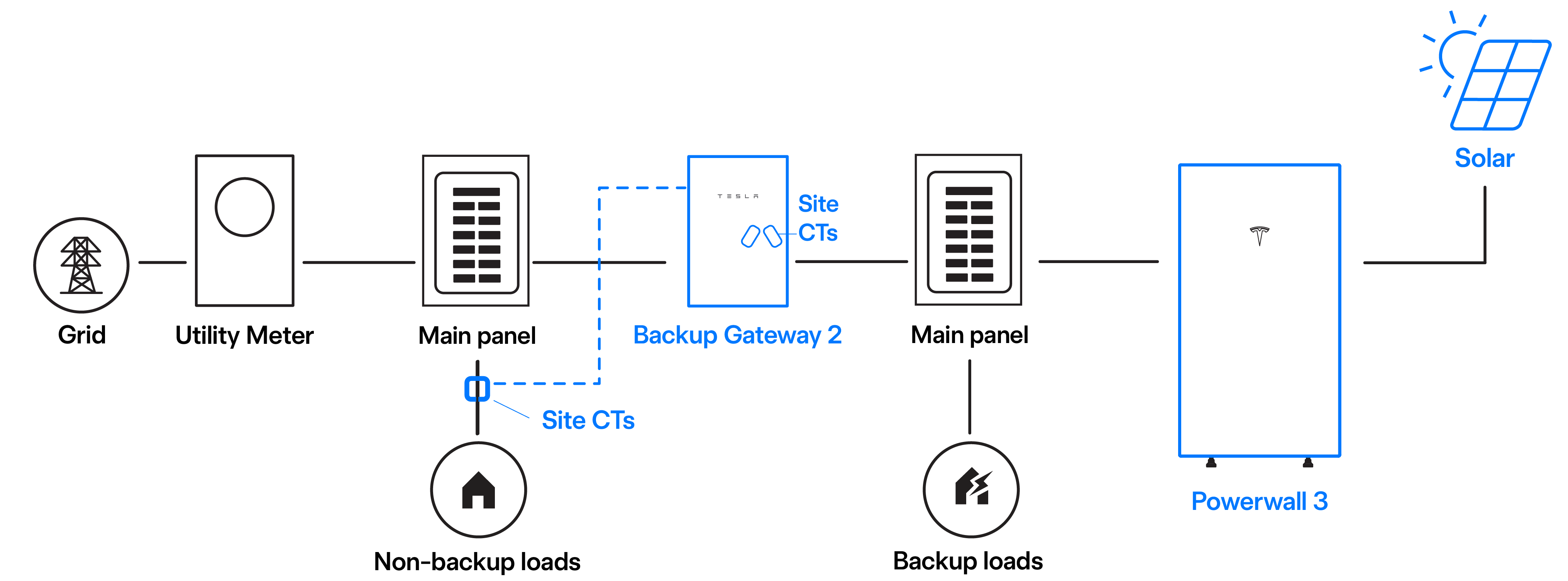
| Site backup loads | Backup Gateway 2 Meter X | Backup Gateway 2 Meter X | Preconfigured as Meter X: Site |
| Site non-backup loads | Backup Gateway 2 Meter Y* | Field-installed Tesla 100 A CTs | Field-configured as Meter Y: Site |
| Powerwall 3 Solar Generation | Powerwall 3 integrated energy meter | N/A | N/A |
*If the non-backup loads were greater than 100 A, or if they were greater than 330 ft (100 m) from Backup Gateway 2, a field-installed Tesla Remote Energy Meter and CTs would be required to monitor them.
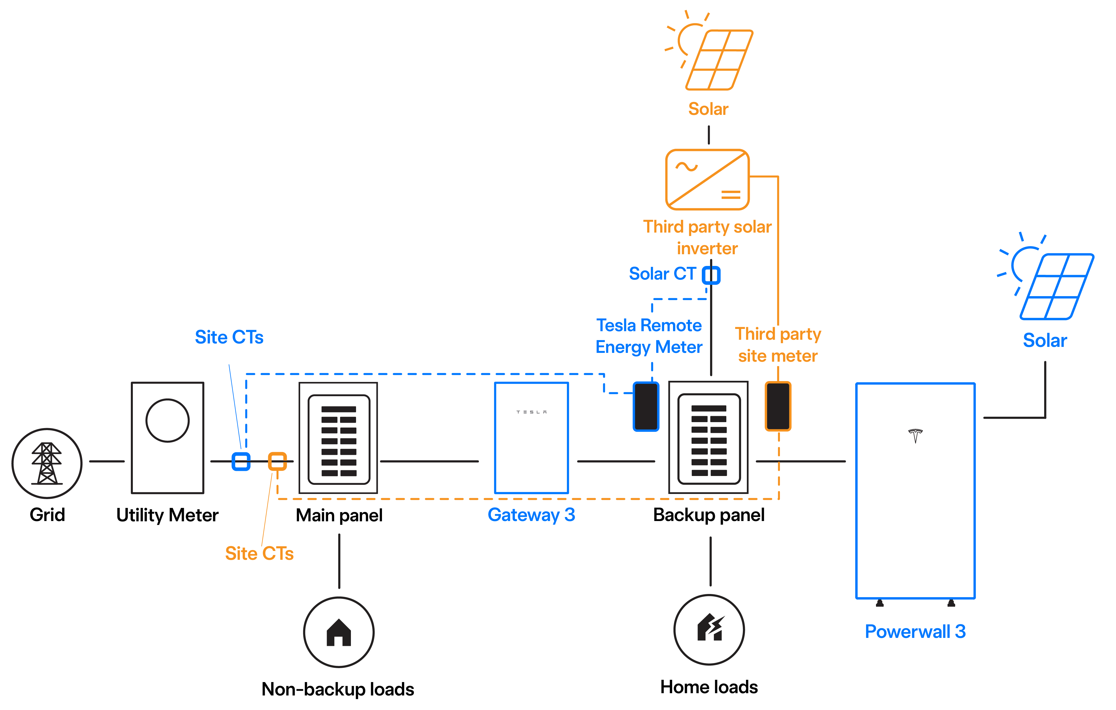
Example 2: Permanent Non-Export System with Uncontrolled Solar Configured for Non-Export
| Energy to be Metered | Meter | CT(s) | Meter Configuration |
|---|---|---|---|
| Site loads (backup and non-backup | Field-installed Tesla Remote Energy Meter | Field-installed 200 A Tesla Remote Energy Meter CTs | Meter paired with Powerwall 3 and CT field-configured as
Tesla Remote Meter: Site Note In this example, the Gateway 3 Meter Z CTs must be
configured as NONE. |
| Powerwall 3 Solar Generation | Powerwall 3 integrated energy meter | N/A | N/A |
| Third party Solar generation | Field-installed Tesla Remote Energy Meter | Field-installed 200 A Tesla Remote Energy Meter CTs | Meter paired with Powerwall 3 and CT field-configured as Tesla Remote Meter: SolarCTx2 |
| Third party Site loads | Third party Site meter | Third party Site CTs | Configured by inverter installer to measure Site |
| Energy to be Metered | Meter | CT(s) | Meter Configuration |
|---|---|---|---|
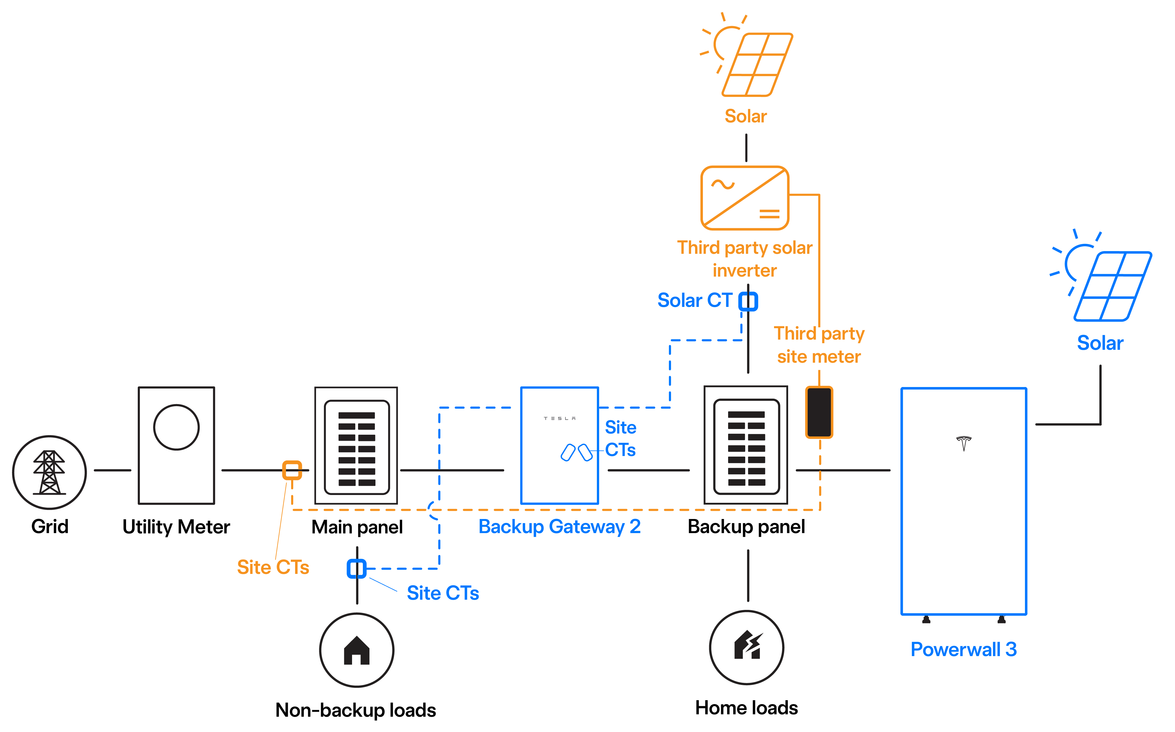
| Site backup loads | Backup Gateway 2 Meter X | Backup Gateway 2 Meter X | Preconfigured as Meter X: Site |
| Site non-backup loads | Backup Gateway 2 Meter Y* | Field-installed Tesla 100 A CTs | Field-configured as Meter Y: Site |
| Powerwall 3 Solar Generation | Powerwall 3 integrated energy meter | N/A | N/A |
| Third party Solar generation | Backup Gateway 2 Meter Y* | Field-installed Tesla 100 A CT | Field-configured as Meter Y: SolarCTx2 |
| Third party Site loads | Third party Site meter | Third party Site CTs | Configured by inverter installer to measure Site |
*If the non-backup loads and/or third party solar were greater than 100 A, or if they were greater than 330 ft (100 m) from Backup Gateway 2, a field-installed Tesla Remote Energy Meter and CTs would be required to monitor them.
Example 3: Permanent Non-Export System with Uncontrolled Solar NOT Configured for Non-Export
| Energy to be Metered | Meter | CT(s) | Meter Configuration |
|---|---|---|---|
| Site loads (backup and non-backup | Field-installed Tesla Remote Energy Meter | Field-installed 200 A Tesla Remote Energy Meter CTs | Meter paired with Powerwall 3 and CT field-configured as Tesla Remote Meter: Site Note In this example, the
Gateway 3 Meter Z CTs must be configured as NONE. |
| Powerwall 3 Solar Generation | Powerwall 3 integrated energy meter | N/A | N/A |
| Third party Solar generation | Field-installed Tesla Remote Energy Meter | Field-installed 200 A Tesla Remote Energy Meter CTs | Meter paired with Powerwall 3 and CT field-configured as Tesla Remote Meter: SolarCTx2 |
| Energy to be Metered | Meter | CT(s) | Meter Configuration |
|---|---|---|---|
| Site backup loads | Backup Gateway 2 Meter X | Backup Gateway 2 Meter X | Preconfigured as Meter X: Site |
| Site non-backup loads | Backup Gateway 2 Meter Y* | Field-installed Tesla 100 A CTs | Field-configured as Meter Y: Site |
| Powerwall 3 Solar Generation | Powerwall 3 integrated energy meter | N/A | N/A |
| Third party Solar generation | Backup Gateway 2 Meter Y* | Field-installed Tesla 100 A CT | Field-configured as Meter Y: SolarCTx2 |
*If the non-backup loads and/or third party solar were greater than 100 A, or if they were greater than 330 ft (100 m) from Backup Gateway 2, a field-installed Tesla Remote Energy Meter and CTs would be required to monitor them.
Configure a System for Permanent Non-Export Mode
- In the Tesla One Device Setup App, go to .
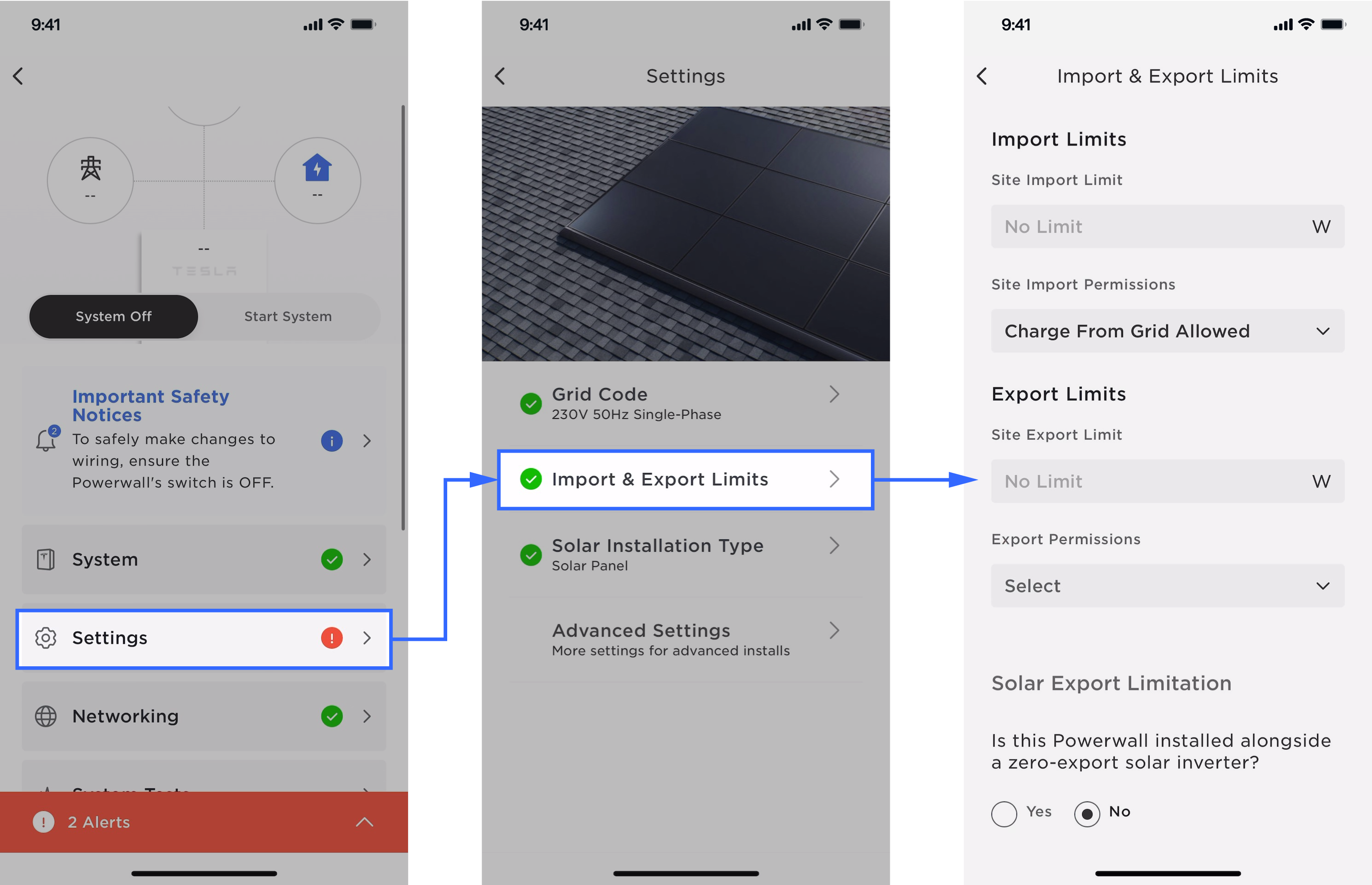
- Set Export Permissions to Permanent Non Export.
- If the system has standalone solar,
uncontrolled by the Powerwall system, determine whether the solar inverter is allowed to
export and if that solar inverter is configured with its own controls to prevent export.
- If it is allowed to export solar, set Solar Export Limitation to No.
- If it is not allowed to export
solar, and is configured with its own non-export controls, set Solar
Export Limitation to Yes.NoteThis provides the Powerwall system with the knowledge that it needs to regulate a small amount of import power to prevent the standalone non-export solar inverter from curtailing. This ensures the best overall system performance for these systems that have two devices both responding to site power measurements.
- Take screenshots of this page and the system Summary page after completing commissioning. These will be required as part of the interconnection submission.