Conductor Limit Feature
Feature Overview
The system can be configured to curtail power from all Powerwalls to limit the total current on a conductor (for example to limit backfeeding a panel). In doing so, the Conductor Limit is equivalent to the "power-source(s) output circuit current" outlined in the requirements of Article 705.12(B) of the NEC/CEC.
To configure a Conductor Limit, two current transformers (CTs) are installed to measure current at the controlled conductor location. Output from these CTs is measured and the data is fed to the Powerwall system. The system then coordinates Powerwall output current amperage to not exceed the current limit in real time.
Application of the Conductor Limits Feature
Conductor Limits can be used to reduce backfeed contributed by Powerwall to more easily meet backfeed compliance on upstream load centers. This application reduces the frequency of main breaker derates and main panel upgrades.
The typical use case for Conductor Limits is to set an amperage allowable backfeed current that is compliant with the upstream load center.
Example 1: Greater than 200 A of Sources in the Generation Panel
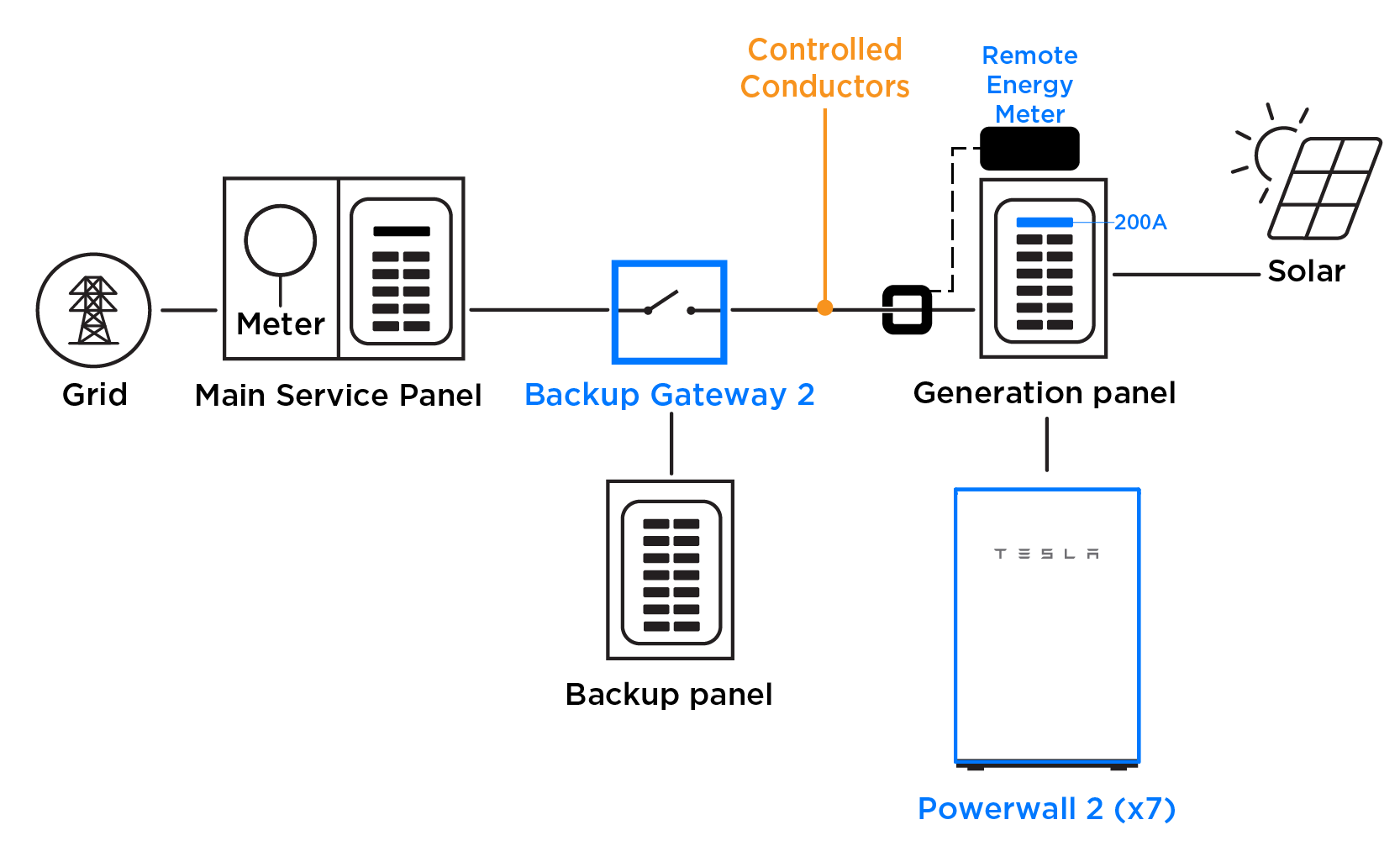
Over 200 A of Powerwalls and PV are being installed in an appropriately sized generation panel (ex: 225 A or 400 A). This generation panel must have a 200 A main breaker to protect the Backup Gateway (200 A rating). To ensure the generation panel main breaker does not trip, a Conductor Limit of 200 A is set.
In the example below, two 200 A Neurio CTs are installed with a Neurio meter and configured as Conductor CTs.
Example 2: Three Powerwalls in System with 200 A Main Panel/200 A Main Breaker
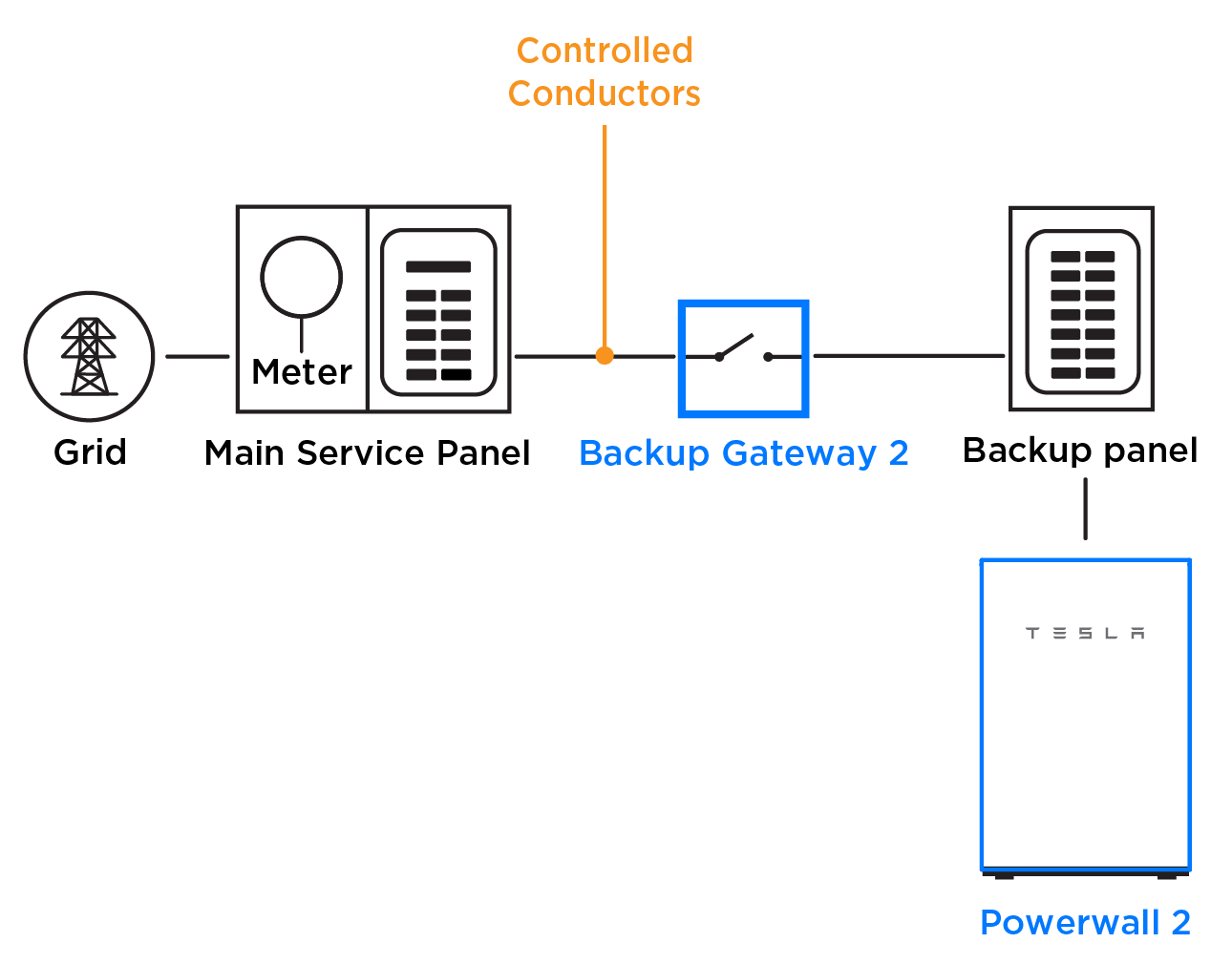
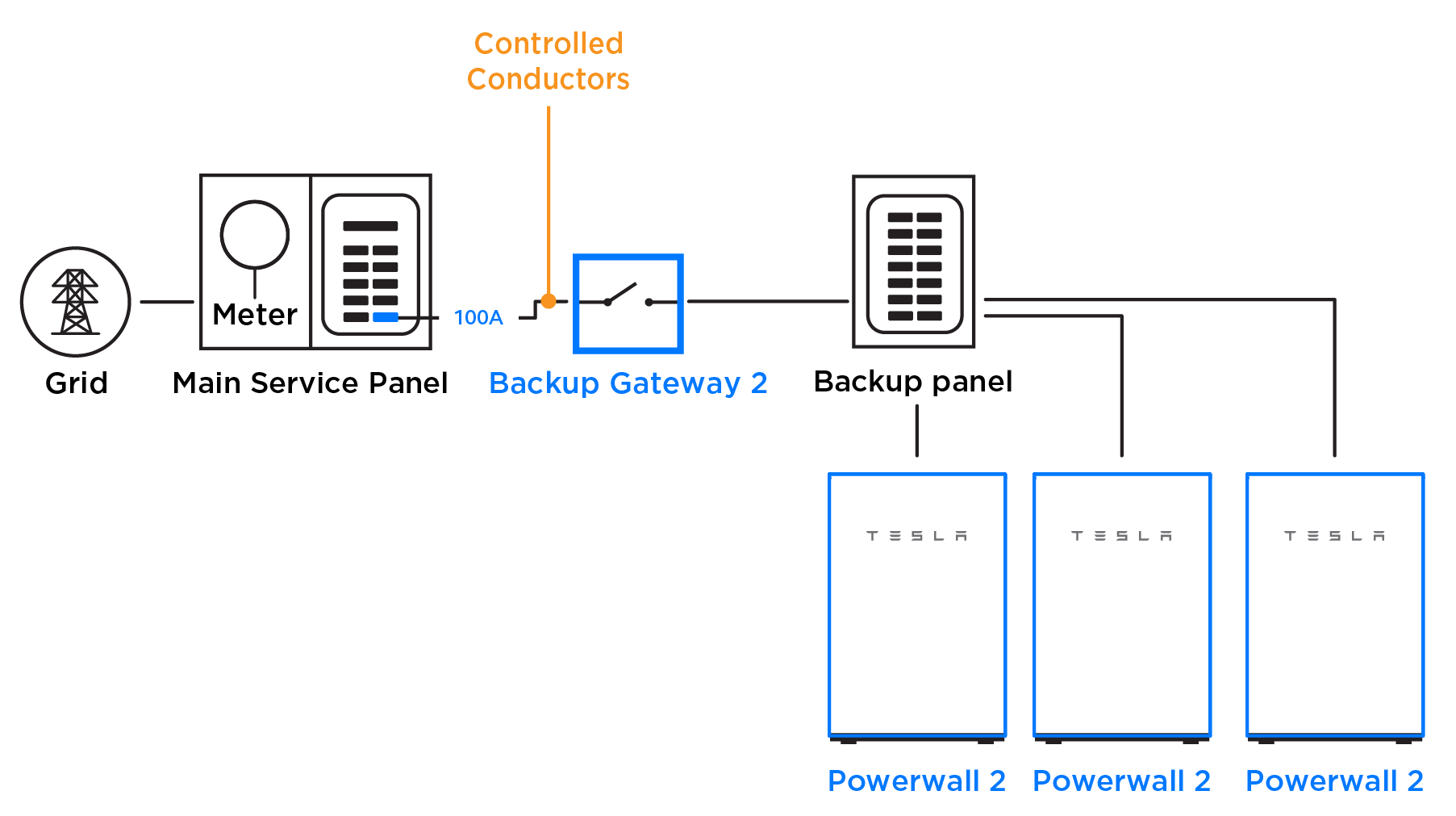
A system has a 200 A main panel rating and a 200 A main breaker. Following the 120% rule, only 32 A of backfeed would be allowed (40 A breaker). The most advantageous solution would be to set a Panel Limit of 160 A.
If setting a Panel Limit is not an option, install the Backup Gateway on a breaker sized for the backup panel (in this example a 100 A breaker is used because the backup panel is 100 A rated) and set a Conductor Limit of 32 A (40 A of equivalent overcurrent protection * 0.8 = 32 A continuous). In this scenario, the Meter X CTs in the Backup Gateway are configured as Conductor CTs.
Example 3: Three Powerwalls in System with 200 A Main Panel/200 A Main Breaker
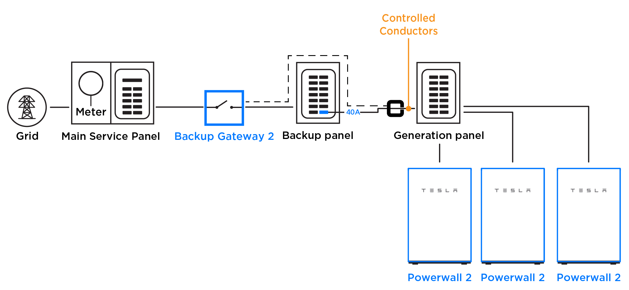
In the instance that a Conductor Limit is not an option for the system (see Examples 1 and 2 for instances where a Conductor Limit is an option), the least advantageous solution is to install the three Powerwalls in a generation panel fed by a 40 A breaker. To prevent the Powerwalls from exceeding that breaker’s capability, install two Conductor CTs and set the Conductor Limit to 32 A (40 A of equivalent overcurrent protection * 0.8 = 32 A continuous).
In the example below, two CTs are connected to Meter Y in the Backup Gateway and configured as Conductor CTs.
Installing and Configuring Conductor CTs
Install Conductor CTs on conductors that are between the grid connection and the Powerwalls, or at a location where Powerwalls have control over current. Ensure the Conductor CTs are oriented the same way as Site CTs (the label faces toward the grid).
Conductor Limits are configured using Tesla One:
- In Tesla One, launch Tesla Device Setup then scan the QR code on the product serial number label to connect to the product Wi-Fi network.
- On the Current Transformers page, configure the CT(s) as Conductor.
- On the Operation Settings page, enter the amperage for the Conductor Limit in the Conductor Export Limit field.