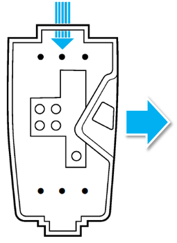
STEPS 2, 3, 4: Preparing and Mounting the Wirebox
This procedure has 4 different variations depending on the chosen wire entry
option, but the general order of steps will be the same for all wire entry options:
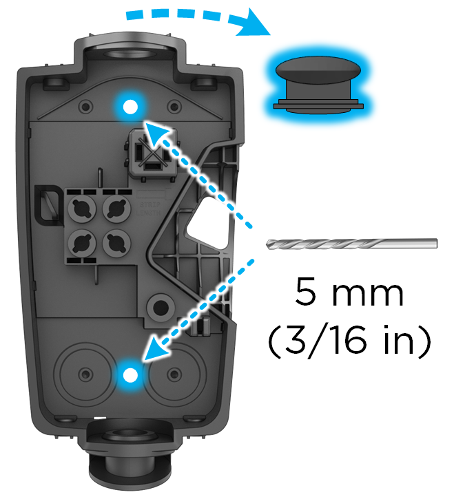
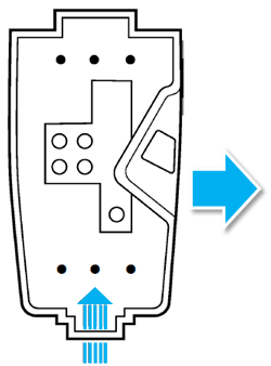
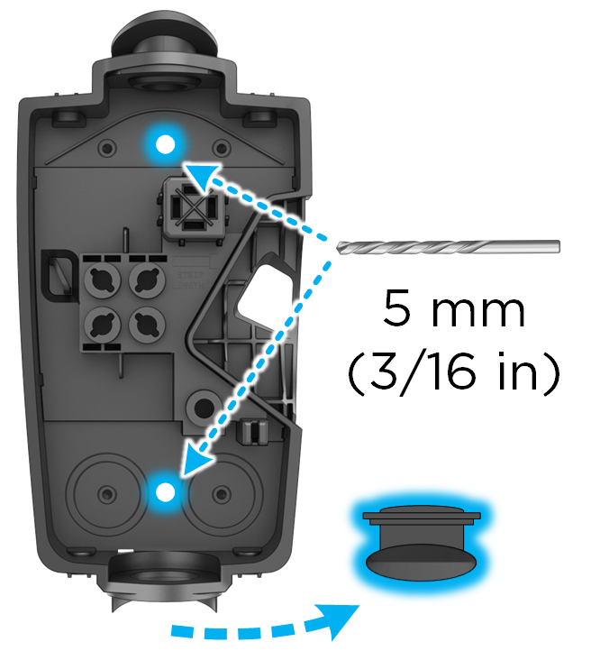
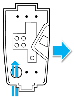
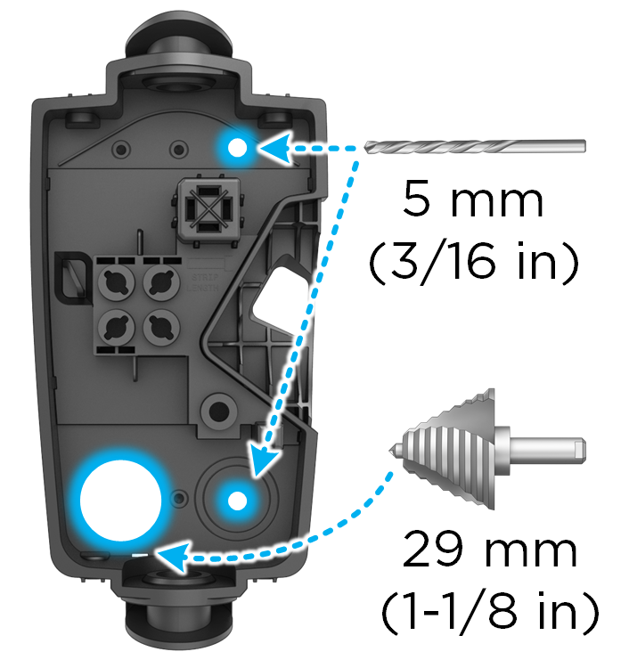
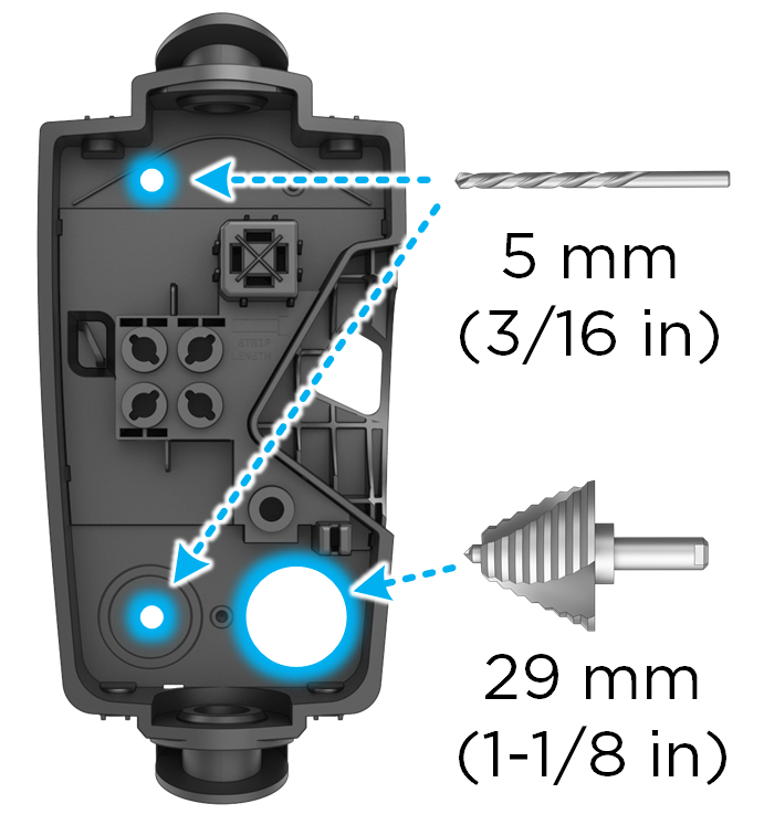
- Drill 5 mm holes into the wirebox*. If wiring for rear entry, use step bit.
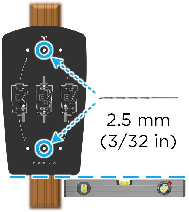
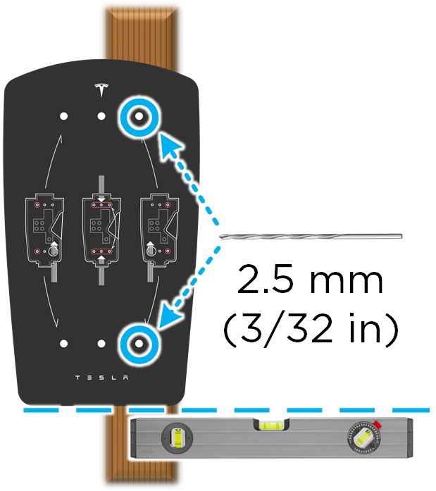
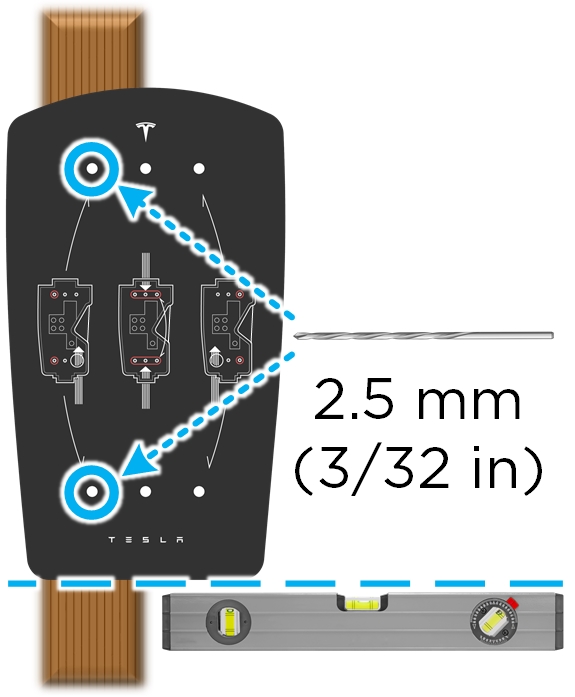
- Use cardboard template to plan or
drill pilot holes into mounting surface*. A 2.5 mm pilot hole is recommended for
most surfaces. NoteDrill larger pilot holes that can accommodate 6 mm wall plugs if installing on concrete, masonry, or similar materials.NoteInstaller can adjust pilot hole size based on mounting surfaceNoteUse a level to ensure that the template is completely level.
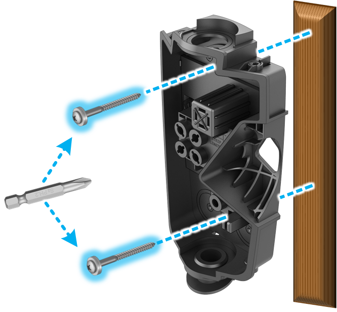
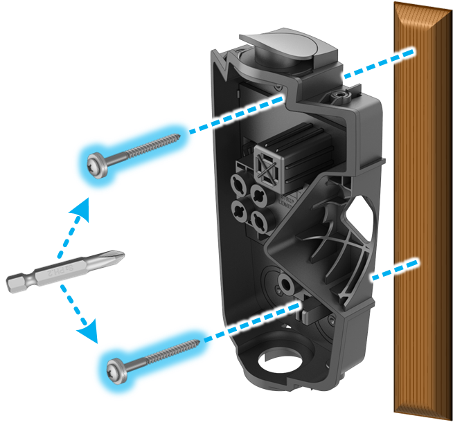
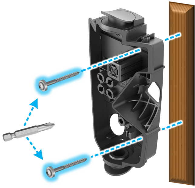
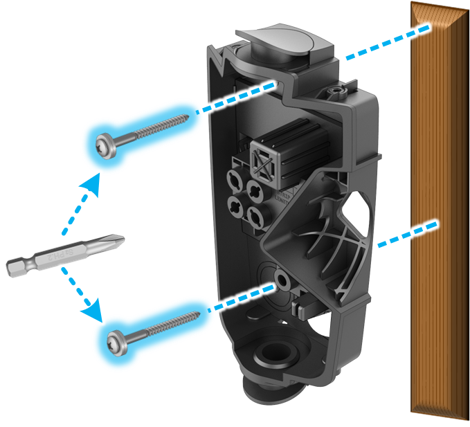
- Attach wirebox to mounting
surface using included fasteners, which include an integrated sealing washer.
The fastener head is compatible with both #2 Phillips or #2 square head bit.
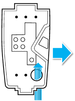
Attach conduit/fittings and bring in conductor wires*.NoteIt is the responsibility of the installer to select appropriate conduit/fitting materials for the installation.
| For Top Entry | 1 | 2 | 3 |
|---|---|---|---|
|
|
|
|
| For Bottom Entry | 1 | 2 | 3 |
|---|---|---|---|
|
|
|
|
| For Rear Left Entry | 1 | 2 | 3 |
|---|---|---|---|
|
|
|
|
| For Rear Right Entry | 1 | 2 | 3 |
|---|---|---|---|
|
|
|
|
CAUTION
Wall Connector is IP
55 rated and does not need caulking. Refrain from using any bonding, sealant, or
adhesives as part of the Wall Connector installation. The provided screws have
sealant washers which provide adequate sealing.
Installer is responsible for providing appropriate glands, fittings, and conduit to secure incoming power supply to Wall Connector wirebox. Top and bottom entry are 28 mm in diameter when sealing plug is removed. If needed, bottom entry can be expanded using a step bit. Do not expand top entry.