Appendix E: (Optional) Install System Shutdown Switch
The Powerwall 3 On/Off switch is also a means of
shutting the system down.
CAUTION
The System Shutdown Switch must be connected to Powerwall 3. Do not connect it to the Backup
Gateway 2, as it will not work.
Install the System Shutdown
Switch
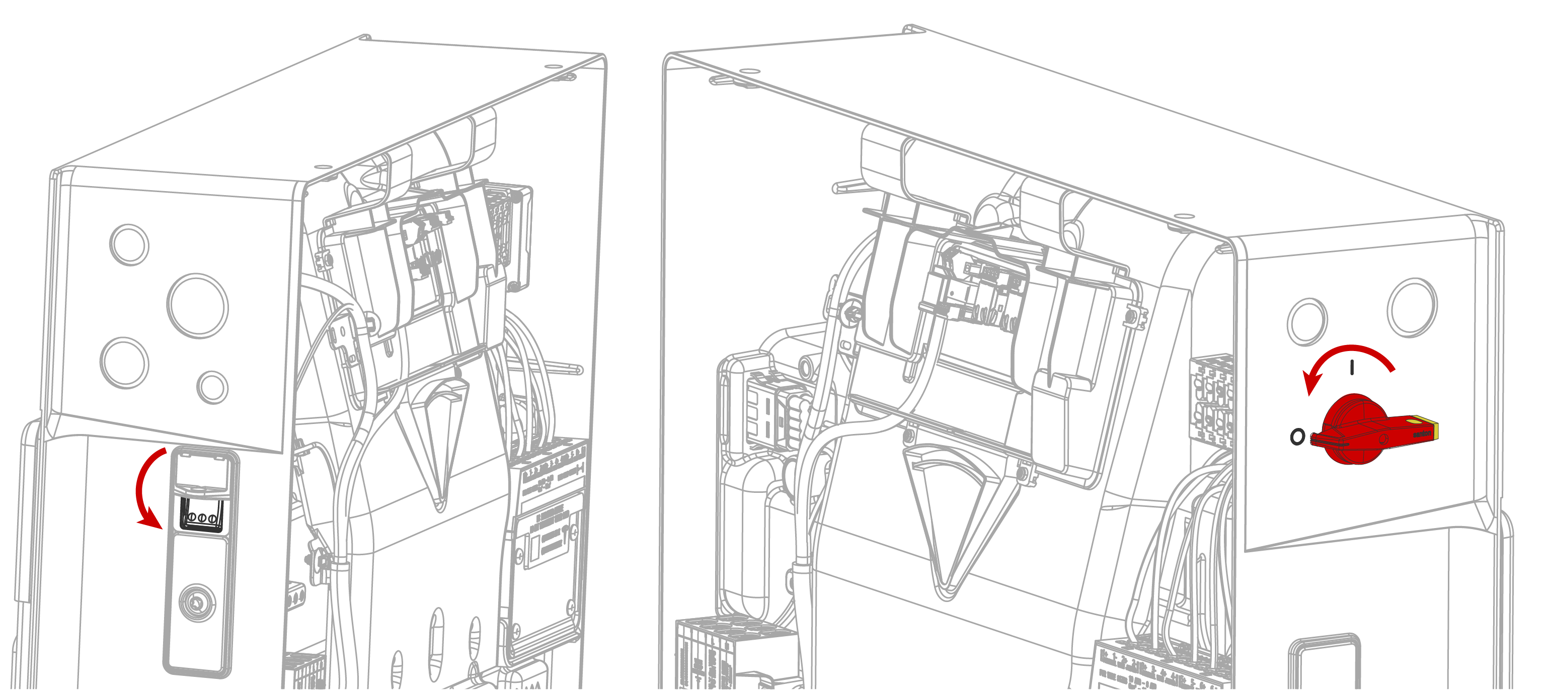
Warning
Before terminating
any conductors inside Powerwall 3, ensure that the integrated DC
isolator and Powerwall 3 On/Off switch are both turned
OFF to de-energize the system. Confirm lack of voltage at the AC and PV terminals
before proceeding.
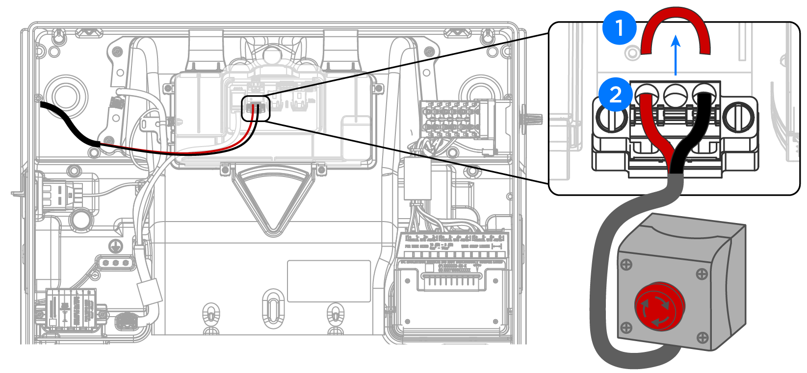
Remove the factory-installed
jumper from the System Shutdown + / - terminals on the Powerwall 3 System Shutdown connector.
See Appendix B: Wiring Reference for a
detailed wiring reference.
Wire the 2-conductor
communication wire (minimum 0.25 mm2 conductors)
to the System Shutdown terminals:
Strip the communication
wire jacket so that it does not extend past the edge of the fan duct.
This ensures the individual conductors lie flat, leaving room for the
front cover to be installed.
Strip each conductor 5/16
inch (8 mm).
Route the two conductors
to the connector as shown below, using the wire management tab to
prevent them from blocking the Tesla Asset Controller.
CAUTION
Tesla
recommends routing the communication wiring into the left side of
the enclosure; always use the wire management tabs to ensure wires
do not block the Tesla Asset Controller. Do not route loose wires
through the front of the enclosure.
Insert a cabinet tip or
electronics tip slotted screwdriver (up to 3/32-inch or 3 mm) into each
screwdriver slot to open the terminal.
Insert each conductor as
far as possible into the terminal and remove the screwdriver from the
screwdriver slot to close the terminal.
CAUTION
Excessive force may damage the connector; do not apply more force
than is necessary to open the terminal and insert the
conductor.
Connect the 2-conductor
communication wire to a suitable DC switch (requirements below).
Switch Requirements
System Shutdown Switches shall meet the following requirements.
Listed or Recognized as
"Emergency Stop Button", "Emergency Stop Device", "Emergency Stop Unit",
meeting one of the following standards:
IEC 60947-1:2020 and IEC 60947-5-1
BS EN ISO 13850:2015 - TC
Rated for at least 12 V, 1 A
Outdoor rated (IP 14 or
higher)
Terminals must accept 0.25
mm2 wire or larger
Recommended Switch Components
The following product (composed of all parts listed below) meets all
above requirements for this application:
Emergency Stop Button Option 1: Eaton
Eaton M22-PVT
Emergency Stop Button
Eaton M22-I1-PG
Emergency Stop Enclosure
Eaton M22-K01PV6
Emergency Stop Contactor Block (240V, 6A)
Emergency Stop Button Option 2: Schneider
Schneider XALD01H7
Emergency Stop Enclosure
Schneider ZB5AT84
Emergency Stop Button
Schneider ZB5AZ009
Emergency Stop Collar
Schneider ZBE102
Emergency Stop Contact Block
Schneider ZBZ1605
Emergency Stop Guard Yellow
Schneider ZBZ1602
Emergency Stop Guard Black
Low voltage communication
wire (Powerwall 3 communication cable preferred)
Installation Guidelines for the System Shutdown Switch
Up to three Powerwall 3 units can be connected to a single System Shutdown Switch
Installed externally in a readily accessible location, preferably near
utility meter
Maximum low voltage wire run from switch does not exceed 150 ft (45 m)
Control circuit must be installed as Type TC-ER or within an appropriate
raceway