Install the Tesla Remote Energy Meter and CTs
Plan Meter and CT Locations
Before installing the meter and/or CTs, ensure none of the following maximum distances are exceeded:

| Distance to Measure | Wiring Option | Tesla P/N (if applicable) | Maximum Distance |
|---|---|---|---|
| Meter to Point of Measurement | CT lead only | 2033376-xx-y | 1.5 m (59 in) |
| If additional length is required: CT extension (3.5 m (138 in) long) | 2060713-xx-y | 8.5 m (335 in) (CT extension (3.5 m) + CT extension (3.5 m) + CT lead (1.5 m) = max 8.5 m) | |
| Meter to Powerwall 3 TACO (RS-485 wired connection) | RS-485 harness | 2045794-xx-y | 1.2 m (4 ft) |
| If additional length is required: 0.2 - 1.5 mm2 communication wiring | Not applicable (wiring supplied by installer) | 50 m (164 ft) | |
| Meter to Breaker | Voltage Harness | Not applicable (included in the kit) | 600 mm (23.6 in) |
| If additional length is required: 1.5 - 6 mm2 AC wiring | Not applicable (wiring supplied by installer) | To maintain accuracy, keep the meter within 61 m (200 ft) of its breaker when using 2.5 mm2 wire |
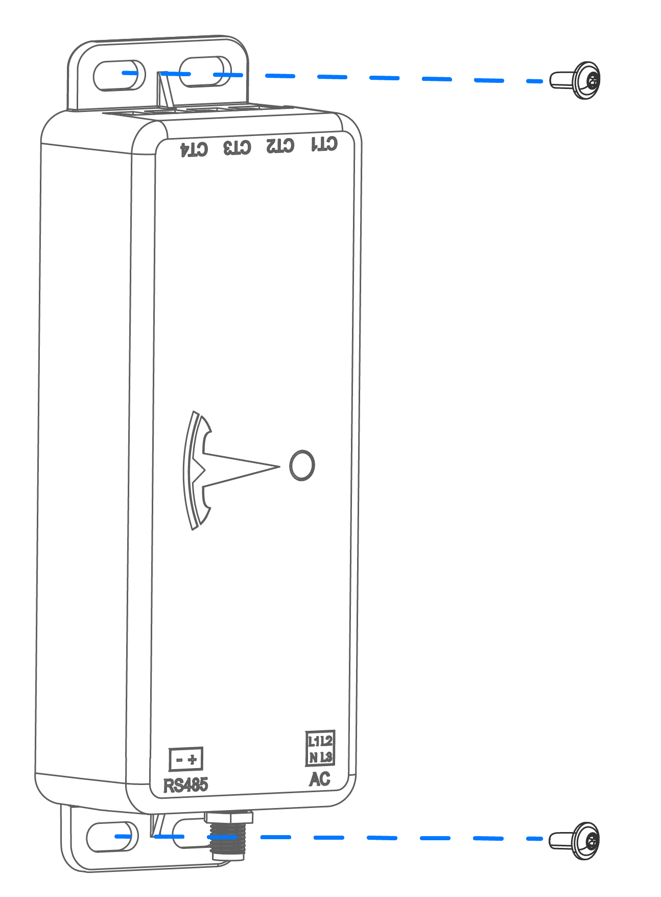
Install the Meter
- Using the screws
provided in the meter kit, attach the meter to the inside of
the main distribution board or to another surface.
- Connect the
voltage line harness leads to a dedicated 16A circuit
breaker of corresponding phase inside the distribution
board.
- Brown Wire: Connect to L1 pole
- Black Wire: Connect to L2 pole
- Gray Wire: Connect to L3 pole
- Blue Wire: Connect the blue wire to the circuit breaker's Neutral pole or Neutral busbar in the distribution board
NoteIf a dedicated circuit breaker is not available, the voltage line harness can be spliced to existing breakers (see Voltage Harness Wiring and CT Placement (1-Phase Service)) - Plug the voltage line harness into the meter (see Location of RS-485, AC, and External Antenna Terminals).
Install the CTs
For measuring the site, the CT must be placed around the corresponding conductor wire in the main distribution board, after the supplier meter and ahead of any loads. If the site includes solar equipment, place an additional CT on the solar conductor wire in the distribution board.
- Plug the
CT into the corresponding CT terminal on the
meter.

- Pinch the
CT to open it, then close the CT around the
conductor(s) being measured.NoteEnsure the CT is installed so that the side with white text on the CT housing pointing toward the power source (service entrance / grid for Site CTs, solar inverter for Solar CTs). Always verify CTs are in the correct orientation by observing power flow in the Tesla One app.
Figure 1. CT Orientation in Relation to Power Flow  NoteEnsure the CT closes completely. If the CT is not closed, it will not measure properly. This is especially relevant if installing a CT around multiple conductors, or around large gauge wire.
Connect Tesla Remote Energy Meter to Powerwall 3
Connection Option 1: Connect Tesla Remote Energy Meter via Wi-Fi:
- Drill a ¼-inch (6 mm) hole in the bottom of the enclosure.
- Route the provided antenna extender through the bottom of the enclosure as shown below.
- Thread the provided lock washer and nut onto the extender, then thread the antenna onto the end of the extender. Secure the antenna against the bottom of the enclosure.

Meter configuration, including pairing the meter via Wi-Fi must be performed during commissioning in the Tesla One app. See Tesla Remote Energy Meter commissioning instructions in the Powerwall 3 Commissioning Guide.
Connection Option 2: Wire Tesla Remote Energy Meter via RS-485:
- Plug the 2-conductor RS-485 harness into the RS-485 terminal on the meter.
- Connect the harness leads to the TACO by
inserting them in the corresponding Remote Energy Meter connector.

TACO Remote Energy Metering Port Pin Terminal Name Wire Gauge 5 RS-485 + 24-16 AWG (0.2-1.5 mm2 or CAT5 (24 AWG) 6 RS-485 -
Meter and CT(s) configuration must be performed during commissioning in the Tesla One app. See Tesla Remote Energy Meter commissioning instructions in the Powerwall 3 Commissioning Guide.