2024-10-24
STEP 5: Connect Powerwall 3 to Backup Gateway
-
Before terminating any
conductors inside Powerwall 3, turn the Powerwall 3 switch OFF to shut the
system down, then turn the integrated DC
isolator OFF.
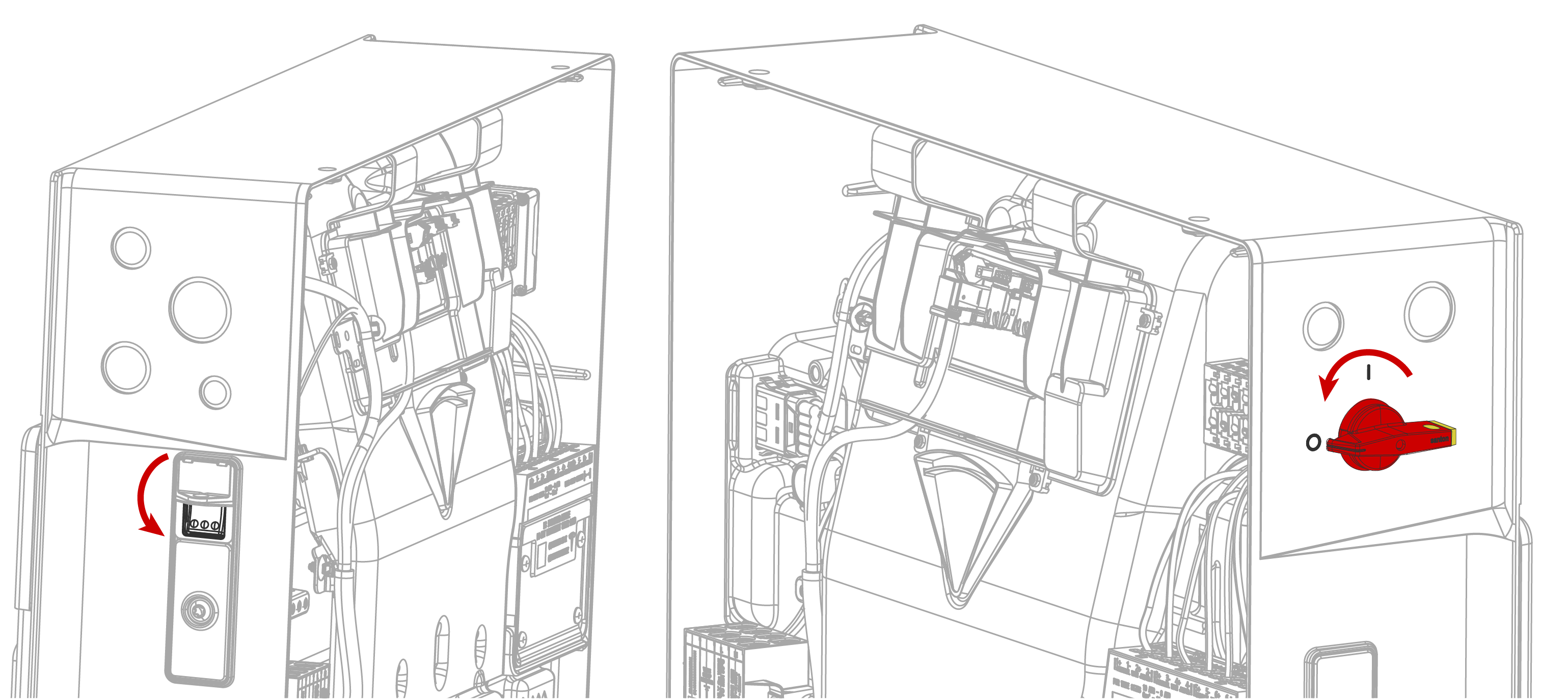 WarningBefore proceeding, confirm both switches are OFF and there is a lack of voltage at the AC and PV terminals.
 -
Run the 4-conductor communication cable from the Backup Gateway through the
conduit or cable gland and pull it into the Powerwall 3 wiring compartment.
CAUTIONAt Powerwall 3, Tesla recommends routing the communication wiring into the left side of the enclosure; always use the wire management tabs to ensure wires do not block the Tesla Asset Controller. Do not route loose wires through the front of the enclosure.NoteSee Plan Cable Length Between Components for the maximum distance between components.
- At the Backup Gateway, strip the communication wire jacket about 76 mm and strip each conductor 8 mm.
-
At Powerwall 3, strip the communication wire jacket so that it does not extend past the edge
of the fan duct and strip each conductor 8 mm.
NoteStripping the communication wire jacket past the fan duct ensures the individual conductors lie flat, leaving room for the front cover to be installed.
- At the Backup Gateway, cut back the drain wire. The drain wire should be terminated at the Powerwall 3 ground terminal only
-
For each connector:
-
Insert each conductor as
far as possible into the terminal and then release the connector lever
to close the connector.
CAUTIONExcessive force may damage the connector; do not apply more force than is necessary to open the terminal and insert the conductor (do not lean on connectors when prying them open).NoteReference Backup Gateway 2 Wiring and Powerwall 3 AC and PV Wiring for the correct wire order in each unit's Communication connector.

-
Insert each conductor as
far as possible into the terminal and then release the connector lever
to close the connector.
- At the Backup Gateway, plug the 4-pin connector into the 4-pin socket labeled "Powerwall". Tighten the screws on the connector.
-
At Powerwall 3:
- Plug the 4-pin connector into the 4-pin socket.
- Wrap the communication cable drain wire around the Protective Earth lead and insert the wires in the equipment grounding terminal. Tighten the screw to 4.5 Nm.