Install Optional Remote Disable Switch
Note
This section provides guidelines on a
system functionality. Please consult your local AHJ or Utility before use.
The Backup Gateway 2 can be wired to include an external Remote Disable switch that simultaneously commands all Powerwalls to become idle and enter a safe mode.
Installation Instructions
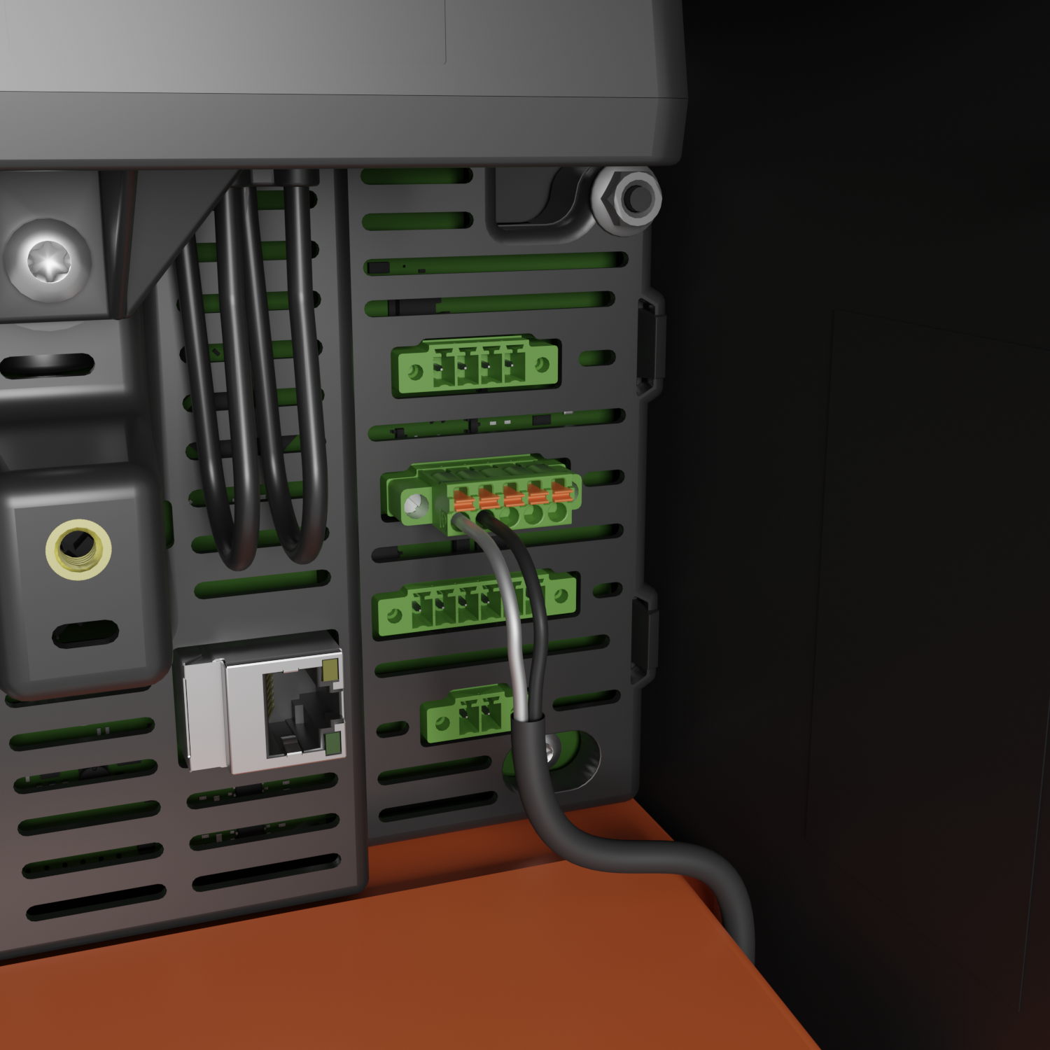
The Remote Disable switch is wired through a low voltage, 12 V DC, control circuit connected to the Gateway AUX port.

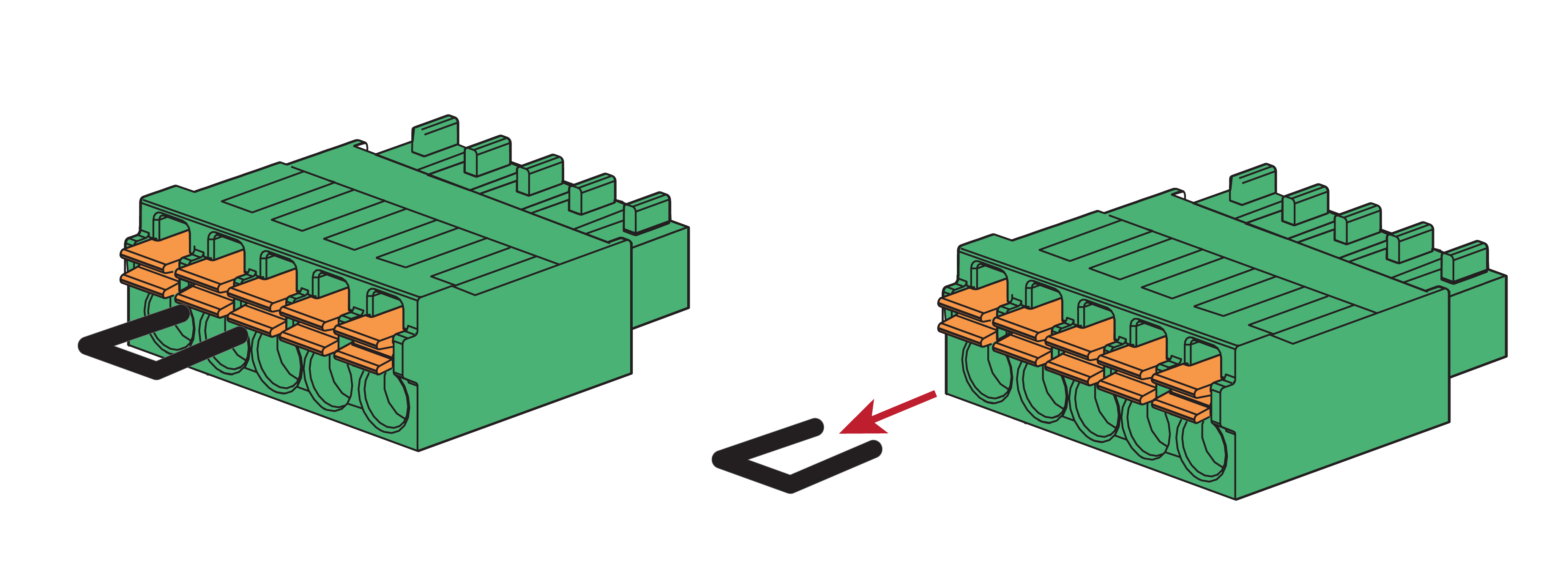
- Remove
the factory-installed jumper from pins 1 and 2 of the 5-position “AUX” connector
inside the Gateway 2. See Appendix B: Wiring Reference for a diagram of the
connector location.

- Using minimum 24 AWG conductors
(maximum 16 AWG), with wiring methods according to code, connect pins 1 and 2
(labeled “SDO” and “SDI”) to a suitable disconnect switch.

- Confirm that all Powerwalls cease operation when the switch is open.
Operation
| Initiate Remote Disable | Turn the switch to the OFF (open) position | |
| All Powerwalls will go to idle. This behavior is the same whether the AC utility grid is present or not. | ||
| Resume Powerwall Operation | Turn the Switch to the ON (closed) position | |
| AC Grid Present | AC grid not present (Off-grid or AC grid is down) | |
| Normal system operation will resume shortly | Powerwall operation will only resume when the grid is back or a 12V jump start is provided to the Gateway | |
Guidelines for Remote Disable Switch Selection and Installation
- Must be Listed or Recognized as "Emergency Stop Button", "Emergency Stop Device", "Emergency Stop Unit"
- Must be lockable in the OFF/open position when necessary to comply with AHJ requirements
- Must have a clear indication of ON/OFF position
- Must be outdoor rated (NEMA 3R or higher)
- Should be installed externally in a readily accessible location preferably near utility meter
- The maximum low voltage wire run from switch to Gateway should not exceed 150 feet (45 m)
- Should observe 12V, 0.1 A ratings