2023-09-05
Step 4: Join the Powerwall Units
- Orient the second Powerwall about 2 cm (1 in) in front of the first, with its back cable entry port facing the hole you drilled in the front of the first Powerwall.
-
(Concealed wiring installations only) Do the following to bridge the gap
between the Powerwall wiring compartments:
- Locate the bridge piece, conduit nipple, two O-rings, and two
insulation bushings.

- Assemble the conduit nipple, bridge piece and O-rings. Center the bridge and O-rings on the nipple.
NoteOrient the O-rings so that the sides with greater surface area (marked “Box Side”) point to the outside, toward the Powerwall chassis.- Install the assembly between the two Powerwalls so it spans the two
wiring compartments.

- Thread an insulation bushing onto each end of the conduit nipple, but do
not fully tighten the bushings.

- Locate the bridge piece, conduit nipple, two O-rings, and two
insulation bushings.
-
(All installations) Locate a side clip, making sure the flange (with magnet) is
positioned at the top and that the cams are rotated vertically in relation to
the clip.

-
Slide the side clip into the gap between the two Powerwalls so that its flanges
engage the side hem of each enclosure.
 NoteThe Powerwall enclosure hems have cutouts that mate with tabs in the clip.
- Press the clip until it is flush with the sides of the Powerwalls.
-
Using the provided 6 mm Allen hex wrench, do the following:
- Turn the top cam 90
degrees clockwise until it clicks into place and stops rotating.
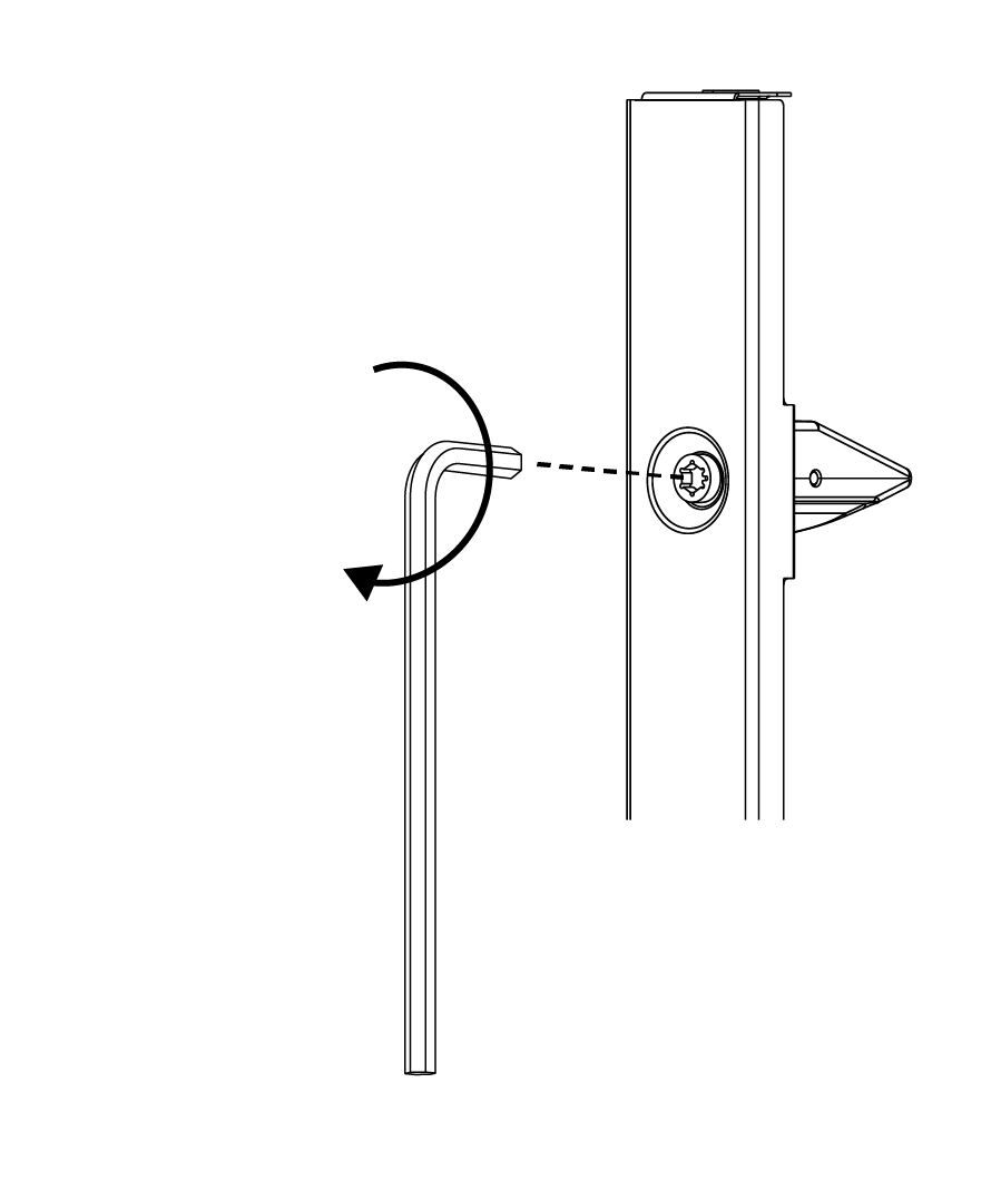
- Turn the bottom cam
toward the wall (toward the first Powerwall) so that the cam indicator
notch on the hex camshaft head points toward the wall, until the cam
clicks into place.

NoteThe top cam is symmetrical and can be rotated in either direction to secure the side clip. The bottom cam must be rotated toward the first Powerwall so that its stepped side (indicated by the notch on the hex camshaft head) engages the housing of one of the Powerwalls. - Turn the top cam 90
degrees clockwise until it clicks into place and stops rotating.
-
Repeat steps 3-6 to install a side clip on the other side of the
Powerwalls.
NoteIf necessary, use a small rubber mallet or a hammer and wood block to gently tap the side clips so that they are fully seated in the hem of the Powerwall.
-
Position the top cover across the gap between the Powerwalls so that its
flanges engage the tops of each side clip. The cover is held in place by the
magnets on the tops of the side clips.

- (Concealed wiring installations only) Tighten the insulation bushing on each side of the conduit nipple to secure the bridge between the two Powerwall wiring compartments.
-
Use shims to ensure that the
Powerwalls are level.
 NoteWhen joined, the units should be level within +/– 2 degrees side-to-side and within +/– 5 degrees front-to-back.