Electrical Equipment Sizing and Overcurrent Protection
Overview
This section describes the requirements for installation of multiple Powerwall units with a Backup Gateway in North America.
Pre-Requisites for Design
Before designing a Powerwall system with more than four Powerwall units:
- AC line impedance must be measured at the installation site to ensure the utility grid connection is able to support the desired quantity of Powerwalls. If the required grid impedance is too high, the Powerwalls may not connect to the grid, resulting in undesirable operation. See Impedance Requirements for Multi-Powerwall Systemsfor maximum impedance values.
- Minimize Impedance:
- Install the Powerwalls as close as possible to the point of interconnection with the grid. The recommended maximum wire length is 33 ft (10 m).
- Install wires larger than required by code between the Powerwall generation panel and the point of interconnection with the grid. Example, if the design requires 3/0 AWG wire, use 4/0 AWG wire.
- Tesla Certified Installers should submit their multiple Powerwall system designs and measured impedance values to Tesla for review by sending design documents to powerwalldesignreview@tesla.com. Copy your Tesla account manager on all submissions.
- Designers must properly size overcurrent protection and loads to account for the full power potential of multiple Powerwalls. For example, a 10-Powerwall system is capable of discharging up to 50 kW of power. See design examples in Panel Configuration and Breaker Sizing.
- Multi-Powerwall installations may require larger Powerwall communication wire between the Backup Gateway and the Powerwall units. Please refer to Required Supplies for communication cable requirements, as your install may require up to #16 AWG or 1.3 mm2 wire.
- For systems between 11 to 20 Powerwalls, multiple Backup Gateways are required, as each Gateway can only control up to 10 Powerwall units. Please refer to the Multiple Gateways on a Single Site application note on the Partner Portal.
- Grid impedance does not need to be measured for off-grid systems as there is no grid impedance to measure.
Pre-Requisites for Installation
Before installing and configuring a multi-Powerwall system:
- Plan for device setup to take longer than a typical installation. It can take up to 3 minutes to complete scan and verify process for each Powerwall, so a 10-Powerwall system can take up to 45 minutes during this stage of device setup.
Service Type and Capacity Requirements
The Backup Gateway supports systems of up to 10 Powerwall units, but the maximum number of Powerwalls may be limited by the site electrical service, utility grid infrastructure, or local requirements; therefore an impedance test is required to confirm.
Line Impedance Requirements
The sensitivity of the system to line impedance increases with the number of Powerwalls in the system. (See Impedance Requirements for Multi-Powerwall Systemsfor the maximum allowable impedance as it relates to number of Powerwalls.)
If grid impedance at a site exceeds the maximum allowable value, do either of the following:
- Decrease the impedance of the site grid connection. This may require coordinating with the local electrical utility. See “Minimize Impedance” in the Pre-Requisites for Design for suggestions.
- Reduce the quantity of Powerwalls installed at the site to meet the maximum allowable impedance value.
If impedance values exceed the requirement for the installed number of Powerwalls, the system may not function properly.
Measuring Line Impedance
To determine the line impedance at a site, measure between Line and Neutral where the Powerwalls will be interconnected to the site electrical system with testing equipment such as the following:
- Fluke 1660 Series Installation Tester (1662, 1663, or 1664)
- Metrel-MI3000 Multifunction Tester
- Megger LTW315 Loop Impedance Tester
Example Line Impedance Test Instructions
For details on line impedance testing, refer to the test equipment manufacturer’s instructions. The steps below are general guidelines only.
- Follow manufacturer instructions to calibrate and zero the impedance tester before taking measurements.
- Complete the test on L1 first, then move to L2.
- Connect all three voltage test leads – Line, Neutral, and Ground
- Follow manufacturer instructions to verify that the correct voltage is present. Switch the tester to a voltage measurement mode and check Line-to-Neutral and Line-to-Ground voltages.
- Follow manufacturer instructions
and take an impedance measurement where the Powerwalls will be interconnected to
the site electrical system. Switch the tester to the appropriate impedance
measurement mode and take the following readings:
- Line-Neutral
- Line-Ground
NoteThe Line-Neutral impedance measurement is the value referenced in Impedance Requirements for Multi-Powerwall Systems. - Record the impedance measurements.
- Repeat steps 3-6 for L2.
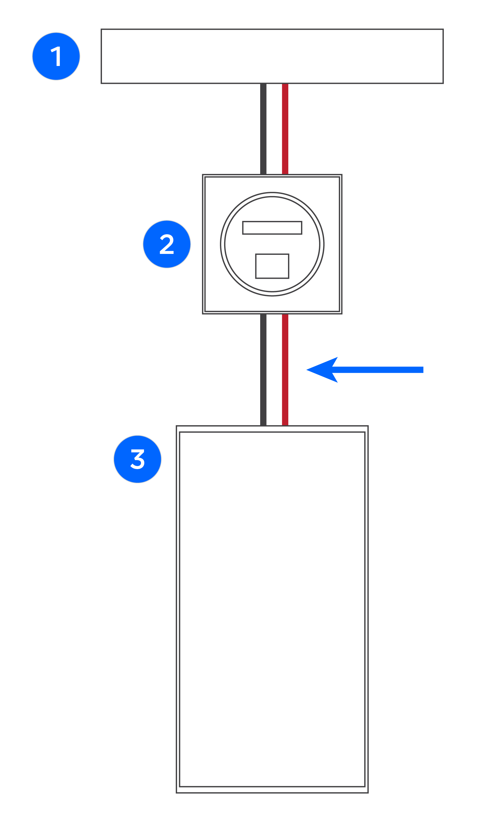
|
1 | Service Entrance |
| 2 | Meter | |
| 3 | Main Panel |
| # of Powerwalls per site | Maximum Grid Impedance, Line – Neutral |
|---|---|
| 1 | 0.80 Ohms |
| 2 | 0.40 Ohms |
| 3 | 0.27 Ohms |
| 4 | 0.20 Ohms |
| 5 | 0.16 Ohms |
| 6 | 0.13 Ohms |
| 7 | 0.11 Ohms |
| 8 | 0.10 Ohms |
| 9 | 0.09 Ohms |
| 10 * | 0.08 Ohms |
| 11 to 12 ** | 0.07 Ohms |
| 13 to 14 ** | 0.06 Ohms |
| 15 to 17 ** | 0.05 Ohms |
| 18 to 20 ** | 0.04 Ohms |
*Maximum number of Powerwalls supported for a single Gateway
**11 to 20 Powerwalls require multiple Gateways
Panel Configuration and Breaker Sizing
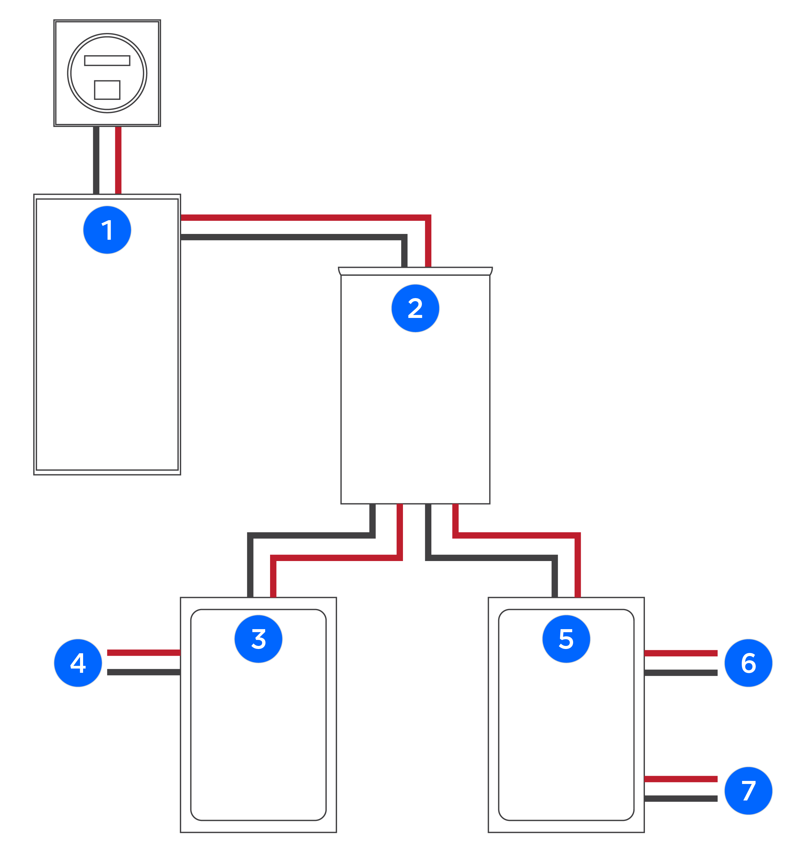
The Backup Gateway has a maximum continuous current rating of 200 A. In systems with 7 or more Powerwall units, to ensure sufficient ampacity while keeping total charge/discharge current within the 200 A capacity of the Backup Gateway, a separate generation panel (400 A minimum) with a 200 A main breaker is recommended. The example below shows the following:
- 400 A main panel with a 200 A main breaker in the panel or in the Backup Gateway
- 400 A generation panel with 200 A main breaker
- Load panel w/ 200 A main breaker
| Example 400 A Service with Separate Generation and Load Panels | ||
|
1 | 400 A Service |
| 2 | 200 A Breaker in Backup Gateway | |
| 3 | 200 A Breaker (max) in 200 A Panel | |
| 4 | Loads | |
| 5 | 200 A Breaker (max) in 400 A Panel | |
| 6 | Solar | |
| 7 | 7 or more Powerwalls | |
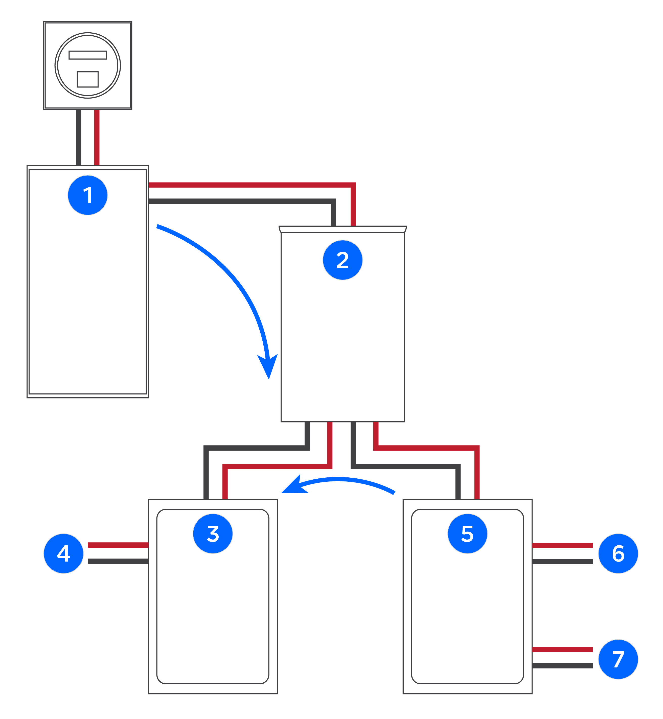
When wiring the load panel, ensure that combined loads do not exceed main breaker continuous or peak current ratings, whether the system is on-grid or off-grid. When the grid is operational, power can flow from both the grid and the generation panel to the load panel.
| Power Flow from Grid and Generation Panel when On-Grid | ||
|
1 | 400 A Service |
| 2 | 200 A Breaker in Backup Gateway | |
| 3 | 200 A Breaker (max) in 200 A Panel | |
| 4 | Loads | |
| 5 | 200 A Breaker (max) in 400 A Panel | |
| 6 | Solar | |
| 7 | 7 or more Powerwalls | |
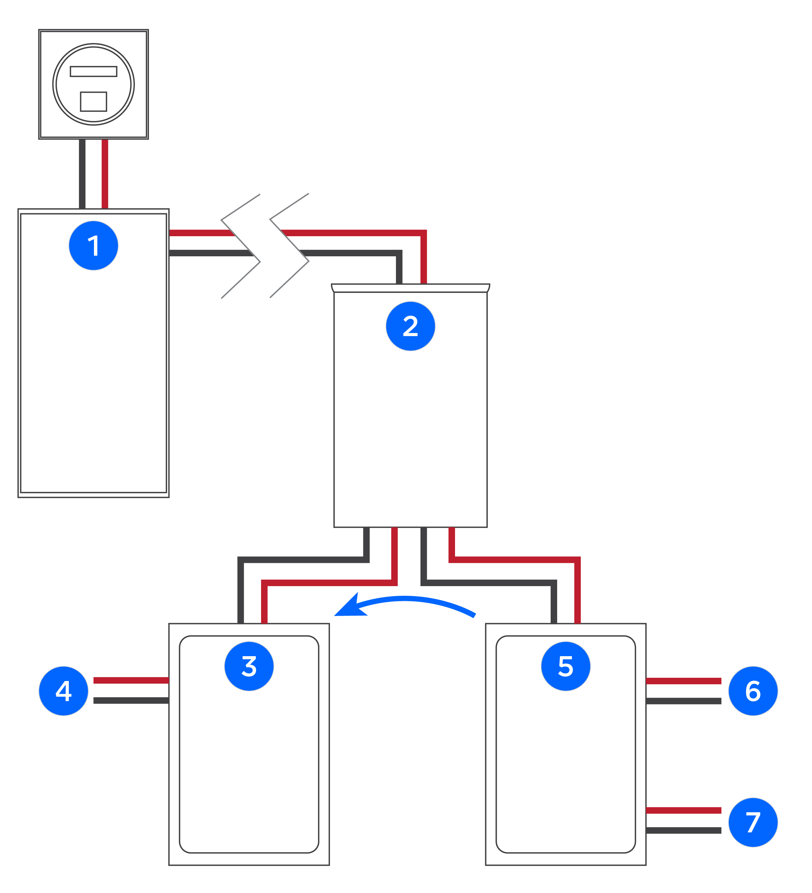
When there is a grid outage, power can flow from the generation panel to the load panel.
| Power Flow from Grid and Generation Panel when Off-Grid | ||
|
1 | 400 A Service |
| 2 | 200 A Breaker in Backup Gateway | |
| 3 | 200 A Breaker (max) in 200 A Panel | |
| 4 | Loads | |
| 5 | 200 A Breaker (max) in 400 A Panel | |
| 6 | Solar | |
| 7 | 7 or more Powerwalls | |