STEP 9: Install Energy Metering for the System
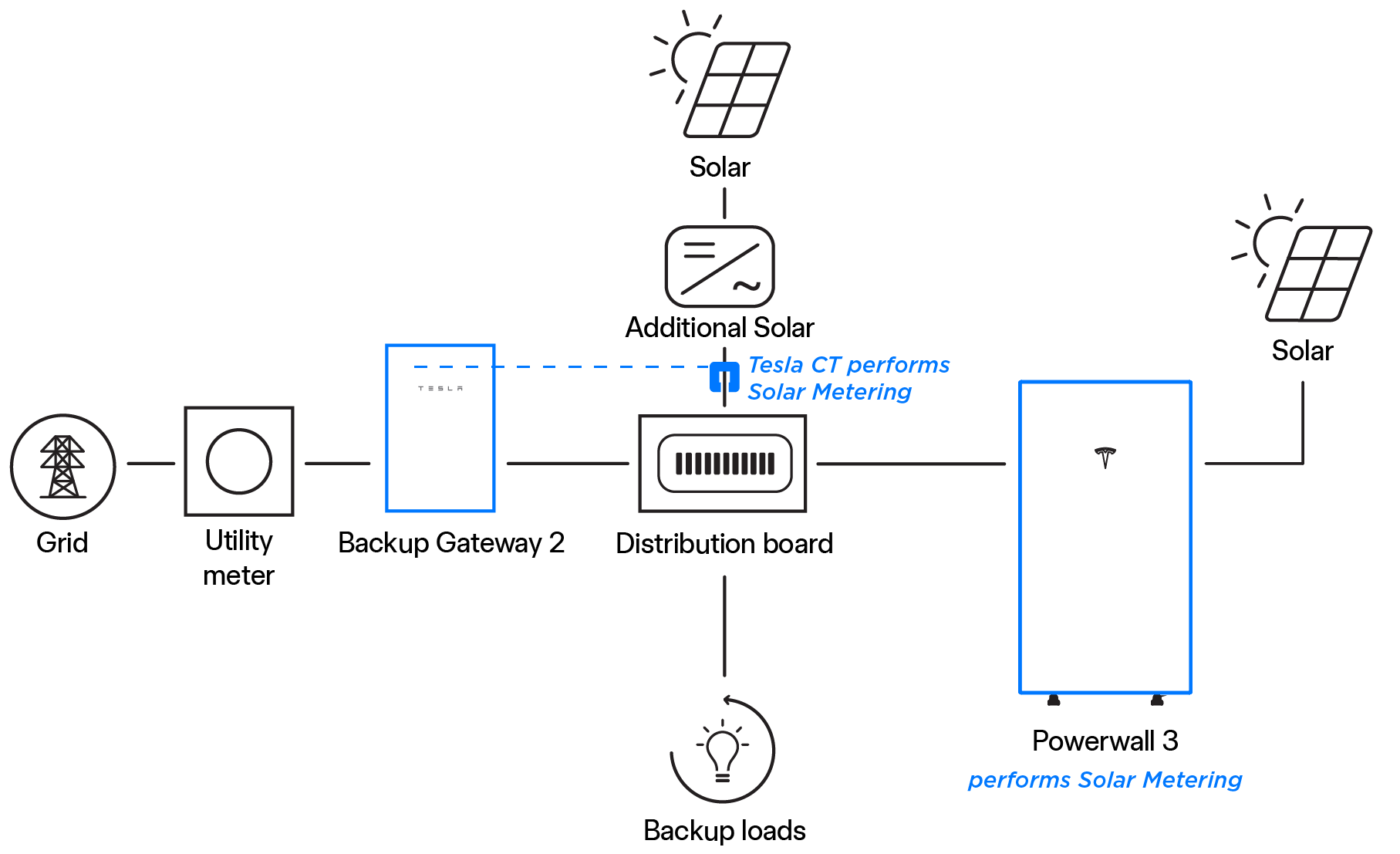
Visibility on power and energy data is needed for the Powerwall 3 system to operate properly. An energy meter accomplishes this by measuring voltage (by voltage tap) and current (by Current Transformer, CT) at certain points in the system.
There are many possible configurations for installing metering depending on system design. However, there are two goals:
- Metering the Site – Site meters show the overall power flow to/from a site from the Grid’s perspective. Thus, Site meter(s) must be installed upstream of all solar production, Powerwalls, and loads.
- Metering Solar – Solar meters capture production from PV inverter(s). There must not be any loads or Powerwalls behind the Solar CTs. This would result in under- or over-estimation of solar production. In this system, Powerwall 3 performs its own Solar metering. Standalone (AC-coupled) solar inverters must be metered by Backup Gateway 2 Meter Y or Tesla Remote Energy Meter.
Site Metering for Backup Gateway 2
Backup Gateway 2 makes metering simple with built-in options for Site metering:
- Internal Primary Meter (Meter X) – This Site meter may be used when the Grid connection is at the Supply terminals. No additional steps are needed during install.
-
Internal Auxiliary Meter
(Meter Y) – If there are any loads or solar upstream of the Supply
terminals, or if the
system includes standalone (AC-coupled) solar, Tesla 100 A CTs
connected to the Internal Auxiliary Meter can be used to measure loads / solar
less than 100 A. One Tesla 100 A CT is included in the Accessory Kit, and
additional CTs (Tesla P/N 1467316-00-x) may be ordered individually.
The Tesla 100 A CTs may be extended a max distance of 330 ft (100 m) by splicing twisted pair or using the Tesla 100A CT Extension (10 ft/3 m) (Tesla P/N 1467274-00-x). Use minimum 600V 20 AWG (0.5 mm2) conductors or larger to extend CTs up to 330 ft (100 m). Voltage rating of the extension wire must be equal to or greater than all other adjacent circuits.
Depending on site layout, it may not be possible to use internal Gateway 2 meters, and Tesla Remote Energy Meter will be required. Tesla 200 A CTs may be extended up to 28 ft (8.5 m) using up to (2) Tesla CT Extension kits (Tesla P/N 2060713-xx-y). See Residential Energy Product Metering Guide for Tesla Remote Energy Meter installation instructions.
Solar Metering for Standalone Solar
- Backup Gateway Meter Y and Tesla 100 A CTs: The CT is connected to the Backup Gateway Internal Auxiliary Meter (Meter Y). Meter Y has three (3) CT ports, and one Tesla 100 A CT is included in the Backup Gateway accessory kit. Additional Tesla 100 A CTs (Tesla P/N 1467316-00-x) may be ordered individually. See Install Tesla 100 A CTs for instructions.
- Tesla Remote Energy Meter and Tesla 200 A CTs: Tesla 200 A CTs may be extended up to 28 ft (8.5 m) using up to (2) Tesla CT Extension kits (Tesla P/N 2060713-xx-y). See Residential Energy Product Metering Guide for Tesla Remote Energy Meter installation instructions.
