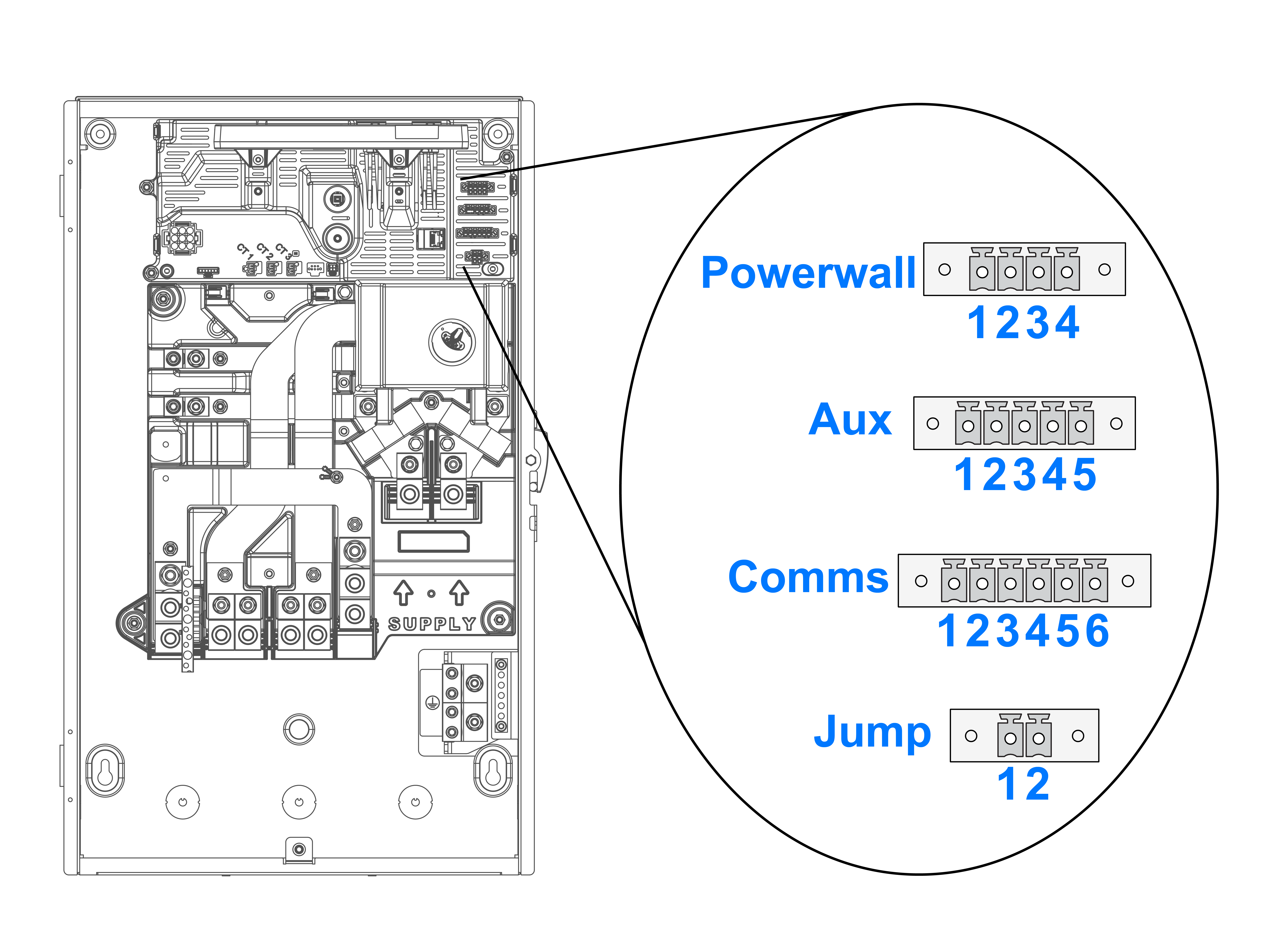
Table 1. Backup Gateway Communication
Wiring
|
Terminal Name |
Recommended Wire Color |
Wire Gauge |
| 1 |
12V + (Logic +) |
Brown |
18 - 16 AWG (0.8 - 1.5 mm2) |
| 2 |
GND (Earth) |
White |
18 - 16 AWG (0.8 - 1.5 mm2) |
| 3 |
CN + (CAN HI) |
Blue |
24 – 16 AWG (0.2 – 1.5 mm2) |
| 4 |
CN – (CAN LO) |
Yellow |
24 – 16 AWG (0.2 – 1.5 mm2) |
Table 2. Aux Wiring
|
Terminal Name |
Recommended Wire Color |
Wire Gauge |
| 1 |
Remote Disable (OUT) |
- |
24 – 16 AWG (0.2 - 1.5 mm2) |
| 2 |
Remote Disable (IN) |
- |
24 – 16 AWG (0.2 - 1.5 mm2) |
| 3 |
Generator / Load Control (+)* |
Red |
18 – 16 AWG (0.8 - 1.5 mm2) |
| 4 |
Generator / Load Control (-)* |
Black |
18 – 16 AWG (0.8 - 1.5 mm2) |
| 5 |
Interlock pin |
- |
24 – 16 AWG (0.2 - 1.5 mm2) |
*These terminals cannot be used for load shedding in Powerwall 3 systems. See Tesla Asset Controller (TACO) Low Voltage and Communication Wiring for the
location of the load shedding terminals on Powerwall 3, and Load Shedding Feature for wiring and
configuration instructions.
Table 3. External Meter Communication Wiring
|
Terminal Name |
Recommended Wire Color |
Wire Gauge |
| 1 |
GND (Earth) / Shield |
- |
24 – 16 AWG (0.2 - 1.5 mm2) |
| 2 |
RS485 HI #1 |
Red |
24 – 16 AWG (0.2 - 1.5 mm2) |
| 3 |
RS485 LO #1 |
Black |
24 – 16 AWG (0.2 - 1.5 mm2) |
| 4 |
GND (Earth) / Shield |
- |
24 – 16 AWG (0.2 - 1.5 mm2) |
| 5 |
RS485 HI #2 |
Red |
24 – 16 AWG (0.2 - 1.5 mm2) |
| 6 |
RS485 LO #2 |
Black |
24 – 16 AWG (0.2 - 1.5 mm2) |
Table 4. Jump Start Wiring
|
Terminal Name |
Recommended Wire Color |
Wire Gauge |
| 1 |
12V |
Red |
24 – 16 AWG (0.2 - 1.5 mm2) |
| 2 |
GND |
Black |
24 – 16 AWG (0.2 - 1.5 mm2) |
