Load Shedding Feature
Overview
Beginning with Powerwall software version 25.2 and Tesla One version 12.32, Powerwall 3 allows for load shedding, meaning a low voltage, dry contact control circuit can be wired to control a specific load. For instance, an air conditioning load controlled by a thermostat can be wired to the Powerwall 3 Aux wiring terminals so that the load can be shed when the Powerwall system is off-grid.
When load shedding has been configured and the Powerwall system is on-grid, the low voltage control circuit is closed and the load is powered. When the system is operating off-grid, the low voltage control circuit is open and the load is OFF.
When the system is wired for load shedding, the controlled load breaker can remain in the backup panel.
Wiring the System for Load Shedding
- Route the low voltage cable to the equipment that is being load shed (in the example below, the cable is routed to the condenser).
- Identify the two existing low voltage control wires at the condenser (in the example below, these wires connect the thermostat to the condenser).
- Remove only one of the low voltage control wires (either wire can be removed).
- Splice the low voltage
control wire to one wire from the low voltage cable that was routed to the
condenser in Step 1. NoteIf installing an override switch, splice the low voltage control wire to the low voltage cable and to the switch (switch requirements defined below). The second low voltage control wire will also need to be spliced to the switch before being connected to the condenser.
- Terminate the second wire from the low voltage cable at the condenser (where the wire was removed in Step 3).
- Route the opposite end of the
low voltage cable to Powerwall 3 and connect the wires
to the Aux
connector.NoteSee Aux Wiring for wiring specifications.
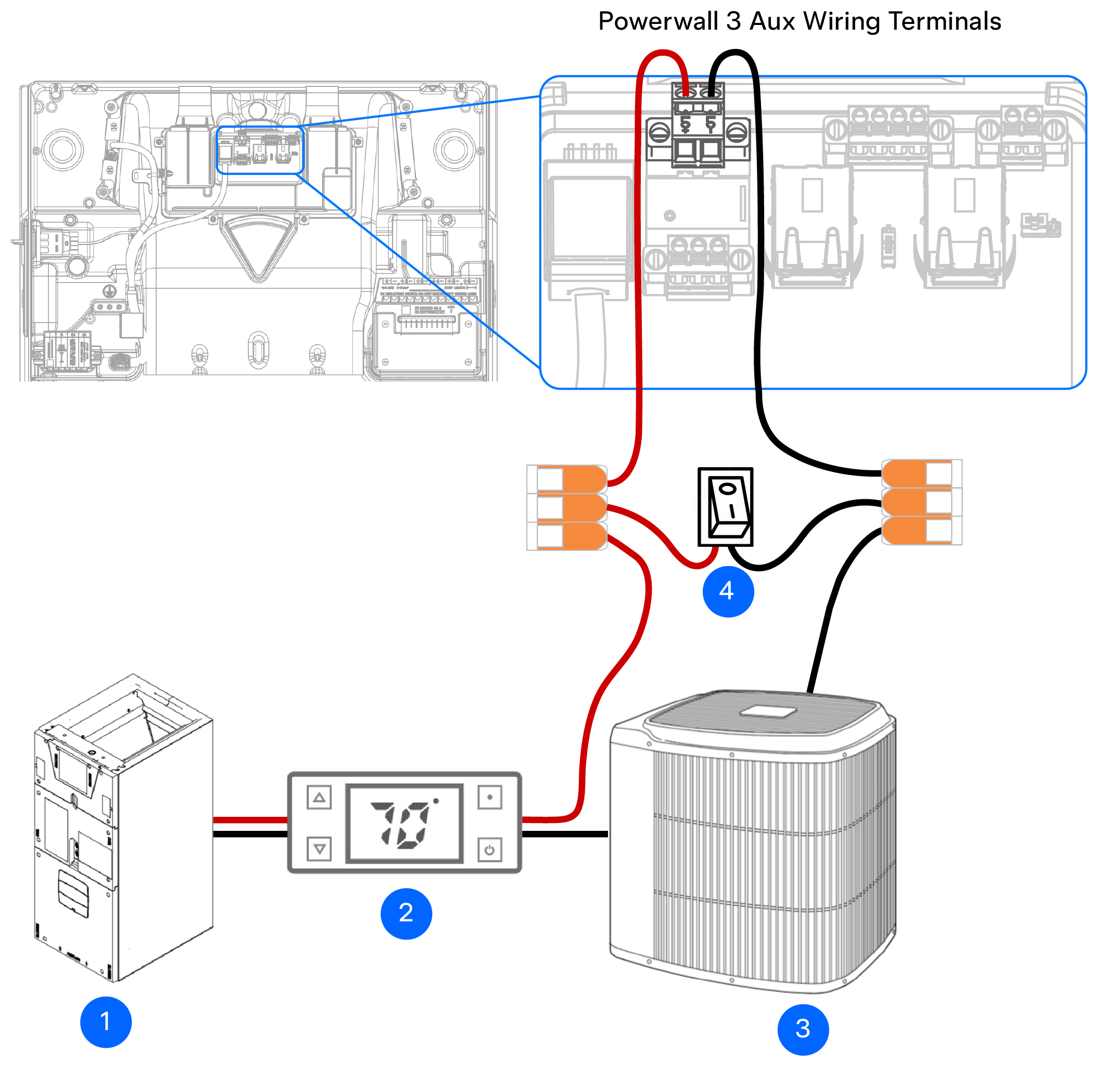
| 1 | Air handler unit |
| 2 | Thermostat |
| 3 | Condenser |
| 4 | Optional override switch1 |
- Rated for at least 60V, 2A
- Outdoor rated (NEMA 3R or higher) if installed outdoors
- Terminals must accept 24 AWG wire or larger
Configure Load Shedding in Device Setup
The load shedding feature must be configured during device setup; see the Powerwall 3 Device Setup Guide for complete instructions to configure the system.
- Select Advanced Settings from the Settings screen.
- Select TACO Load Control Relay.
- Select Off-grid Load Shedding from the Configuration Type menu, then select Done.
Backup Gateway 2 Systems Only: Configure Gateway Load Control Relay
For Powerwall 3 systems installed with Backup Gateway 2, a low voltage, dry contact control circuit can also be connected to the Backup Gateway 2 Aux terminals (see Aux Wiring for wiring specifications). For these systems, up to two low voltage control circuits can be connected, with one connected to Powerwall 3 and the other connected to Backup Gateway 2. If connecting only one low voltage control circuit, the installer can choose either the Powerwall 3 or the Backup Gateway 2.
To connect a low voltage control circuit to Backup Gateway 2, follow the steps outlined above, but route the low voltage cable to Backup Gateway 2 and connect the wires to terminals 3 and 4 on the Aux connector:
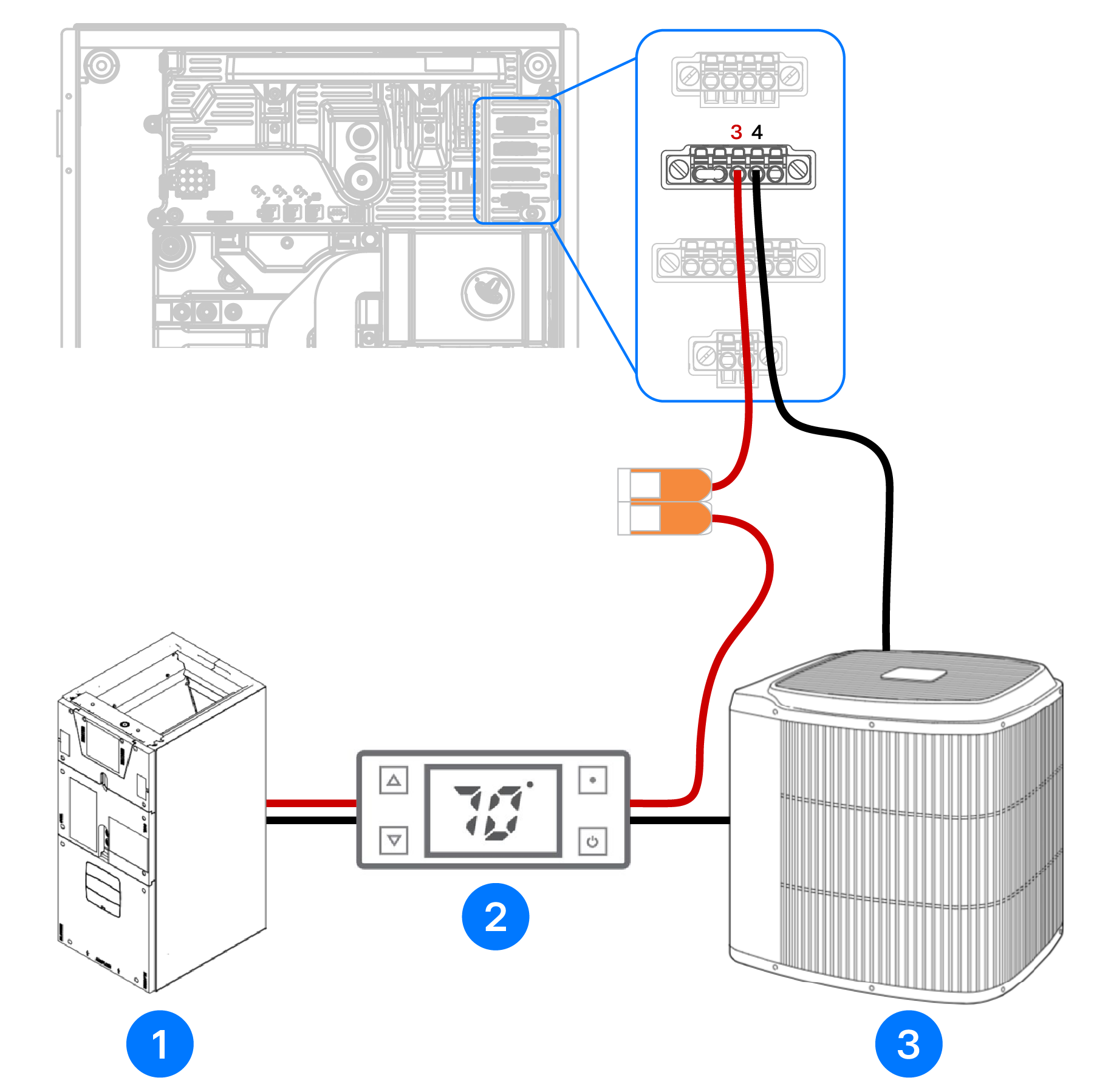
| 1 | Air handler unit |
| 2 | Thermostat |
| 3 | Condenser |
- Select Advanced Settings from the Settings screen.
- Select Gateway Load Control Relay.
- Select Off-grid Load Shedding from the Configuration Type menu, then select Done.