Install Optional Internal Panelboard in the Backup Gateway
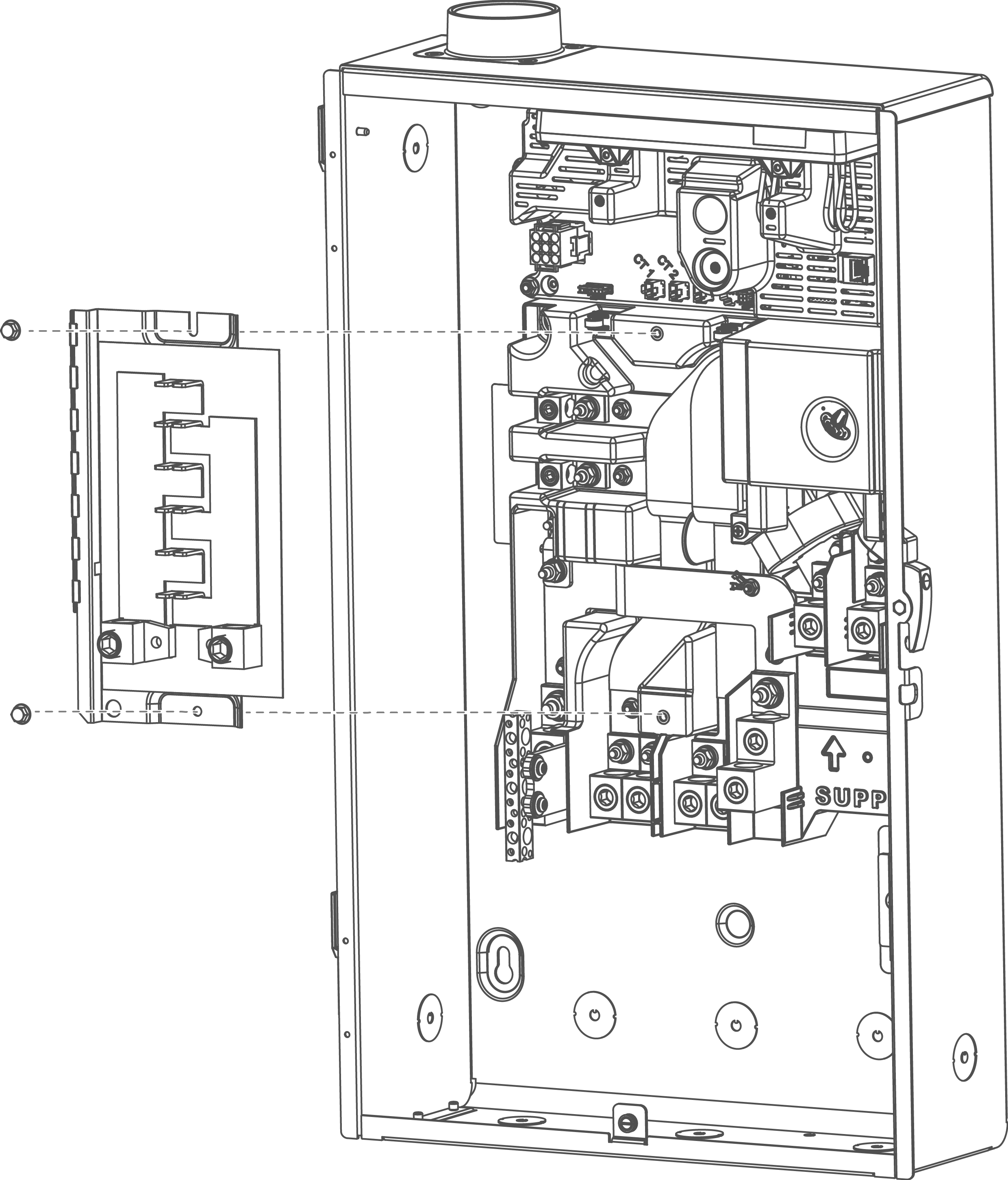
The Internal Panelboard kit (Tesla P/N 1529623-00-x) may be installed in the Backup Gateway 2 and connected to either the Backup or the Non-Backup terminals by feeding a two pole breaker on the bussing.
- Mount the Internal Panelboard into
the Backup Gateway using the provided mounting screws (M5x12 hex bolts).

- Connect the internal panelboard to
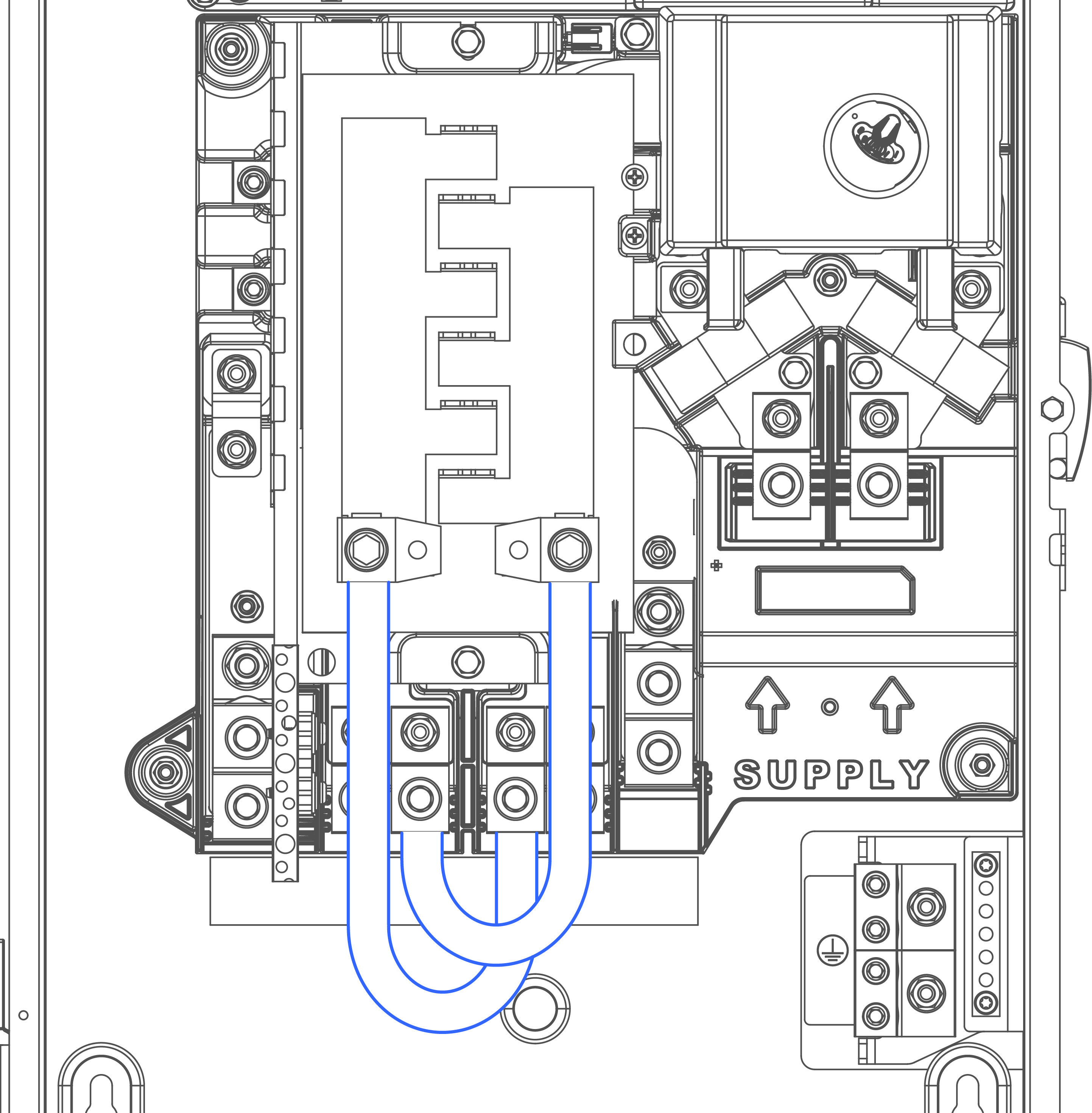
either the Backup (2a) or Non-backup (2b) lugs:
- Connect the L1 and L2 lugs on
the bottom of the Internal Panelboard to the Backup lugs via the provided
105°C-rated CU wire jumpers.

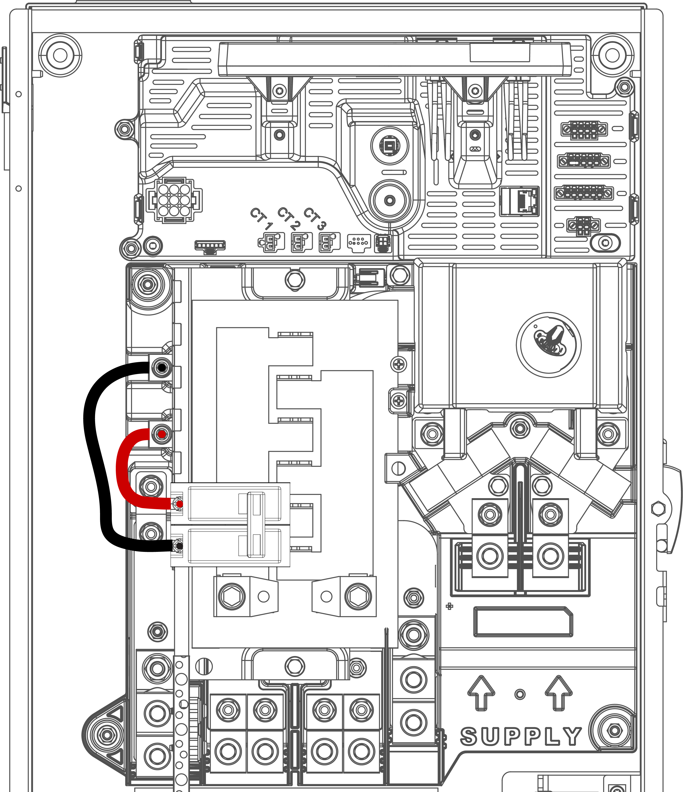
- Connect the Non-Backup Lugs to an acceptable branch breaker on the bussing
(up to 100 A).

NoteThe branch breakers are required when connecting the internal panelboard to the Non-Backup lugs to accommodate for wire gauge difference (see Backup Gateway 2 Wiring for wire gauge ranges, and Acceptable Circuit Breakers for acceptable branch circuit breakers). - Connect the L1 and L2 lugs on
the bottom of the Internal Panelboard to the Backup lugs via the provided
105°C-rated CU wire jumpers.
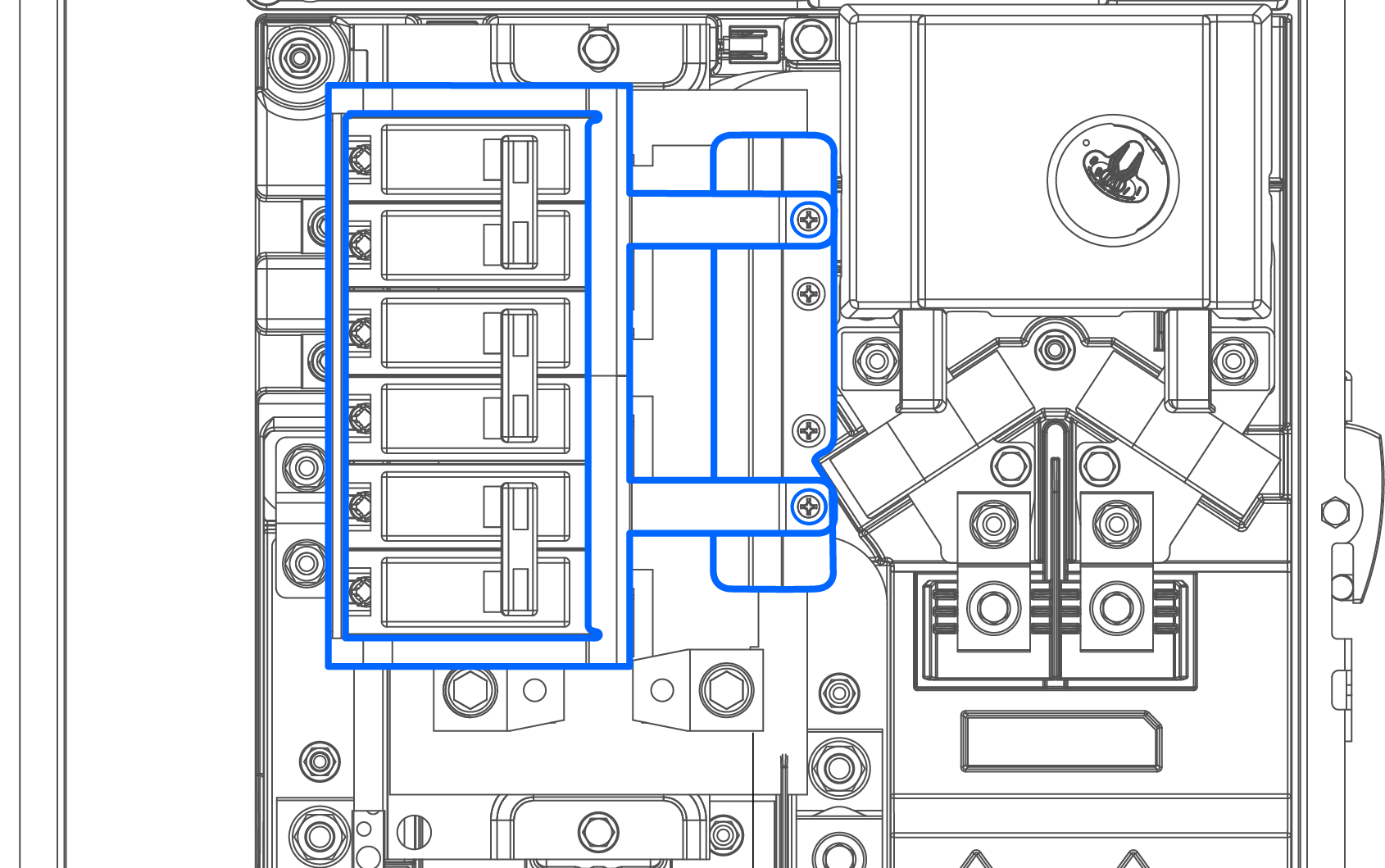
- Once all breakers have been
installed, install the breaker hold-down if installing any back-fed or generation
breakers on the bussing. Mount the hold-down bracket using the provided (2)
M5-0.8x12 Philips head screws.

- Place the adhesive circuit label on the deadfront to label circuits.
Design Considerations
The Internal Panelboard is a 200 A-rated copper bussing that supports (6) 1 inch breaker spaces (12 circuits) using acceptable branch circuit breakers up to 125 A maximum (see Acceptable Circuit Breakers for acceptable branch circuit breakers).
The Powerwall+ connection to the Backup Gateway always requires a 50 A circuit breaker. This breaker serves as circuit protection for the Powerwall+. Breaker sizing and installation must comply with the National Electric Code.