System Shutdown Switch Connected to Backup Gateway
As noted in STEP 7: Install System Shutdown Switch, a System Shutdown Switch can be wired to the Powerwall+ solar assembly to manually initiate Rapid Shutdown (RSD) to disable solar output and simultaneously command all battery assemblies and Powerwall 2 units to enter a safe mode.
The switch can also be connected to the Backup Gateway AUX terminals, although this method does not meet RSD requirements. The following section outlines system behavior when the System Shutdown Switch is connected to the Backup Gateway, as well as instructions for wiring the switch.
Note
Beginning with Powerwall software
version 21.39.1, all shutdown switches (including the external System Shutdown Switch
described here) will shut down all CAN-connected components when activated. The
following table defines System Shutdown Switch behavior for systems on software version
21.39.1 or later; for systems on software versions earlier than 21.39.1, see Rapid Shutdown Initiation
Note
Turning the Enable switch on each
Powerwall+ OFF will also shut down all
equipment.
| Action | System Behavior | |
|---|---|---|
| Turn Switch to OFF (open) Position |
|
|
| Turn Switch to ON (closed) Position | The solar assembly performs a system self-test and then resumes operation | |
| AC Grid Present | AC Grid Not Present (Off-grid or AC Grid is Down) | |
| Normal system operation will resume shortly | Battery operation may only resume when the grid is back or a 12V jump start is provided to the Gateway | |
CAUTION
Before performing
maintenance on the system, use a multimeter to check for voltage after shutting down
equipment to ensure the system is in a safe state.
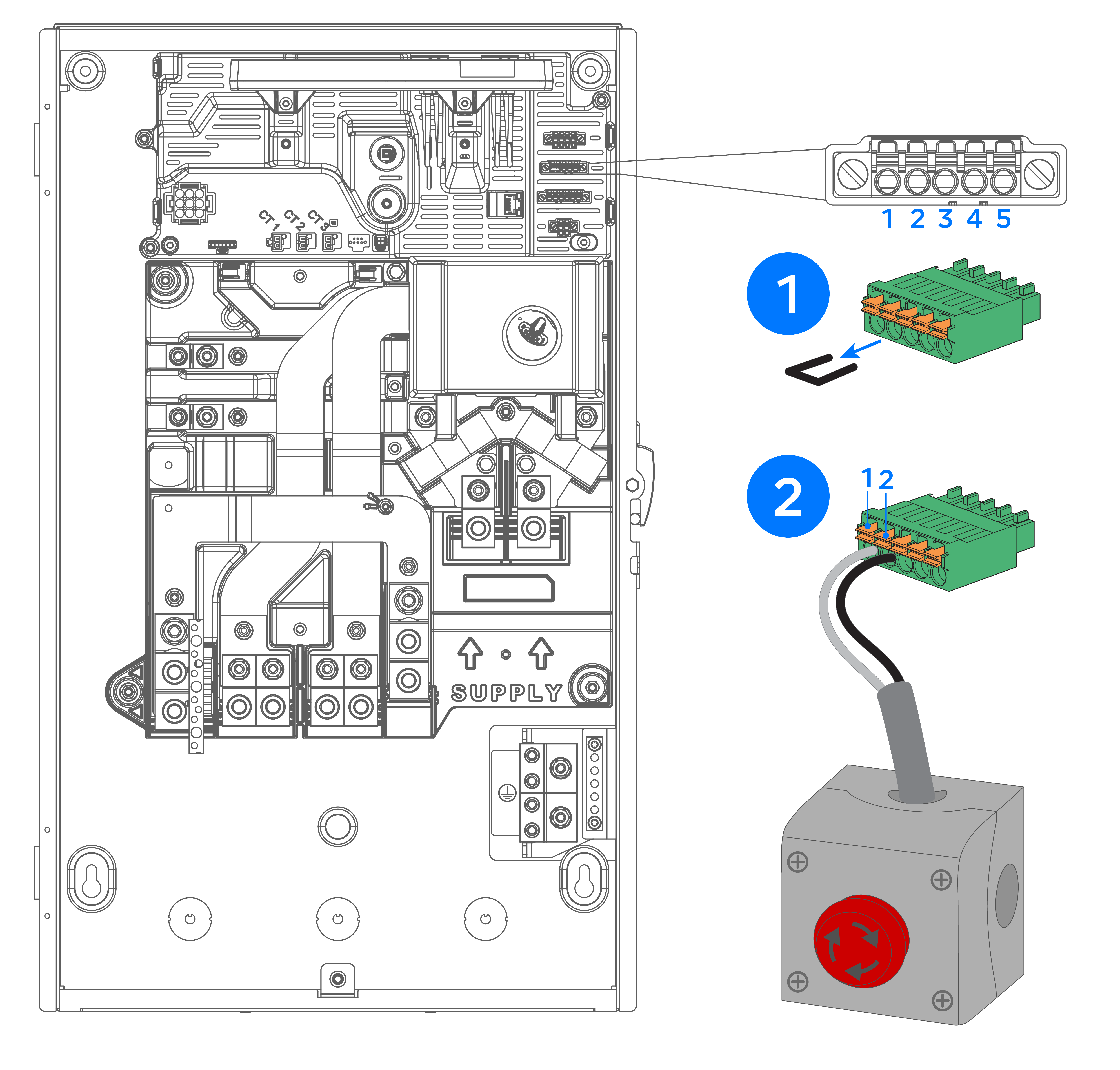
Connect the System Shutdown Switch to the Backup Gateway
To wire the System Shutdown Switch to disable all solar output and command all
battery assemblies and Powerwalls to a safe mode, connect the switch to the Backup
Gateway:
- Remove the factory-installed jumper from pins 1 and 2 of the 5-position “AUX” connector inside the Gateway 2. See Appendix B for a diagram of the connector location.
- Using minimum 24 AWG
conductors, with wiring methods according to code, connect pins 1 and 2
(labeled “SDO” and “SDI”) to a suitable disconnect switch (requirements
below).
Note
To meet RSD requirements
the switch must be connected to the solar assembly RSD IN/OUT terminals (not the
Backup Gateway AUX terminals).
Note
For switch requirements, recommended
components, and installation guidelines, see STEP 7: Install System Shutdown Switch.