Mounting Bracket Anchoring Details

A2

Informational PurposesAn informational icon, calling your attention
Note
The details below are minimum guidelines and are not guaranteed to be applicable.
Informational PurposesAn informational icon, calling your attention
Note
All fasteners shall be galvanized or stainless steel for exterior applications.
Informational PurposesAn informational icon, calling your attention
Note
All wall framing referenced in the details must be part of the home's main permitted bearing wall and/or lateral force resisting system. The contractor and their licensed design professional are responsible for ensuring the walls, and their load transfer connections, are structurally sound to support all code-specified vertical and lateral loading imposed by the equipment.
Informational PurposesAn informational icon, calling your attention
Note
At the contractor's expense and with no liability to Tesla, the homeowner and contractor can work with a third party licensed engineer and AHJ to develop alternative supports.
Informational PurposesAn informational icon, calling your attention
Note
Do not mount below or above windows of the same story wall. Mounting equipment on fences, half walls, retaining walls, or other non-structural construction is not allowed. Supporting framing must be part of a permitted structure and any unusual framing near the mounting area that may compromise the wall's integrity shall be evaluated by the contractor and their licensed design professional.

A3 - Mounting Bracket Anchoring Details

Wood Studs (spaced at 12, 16, 20 or 24 inches)

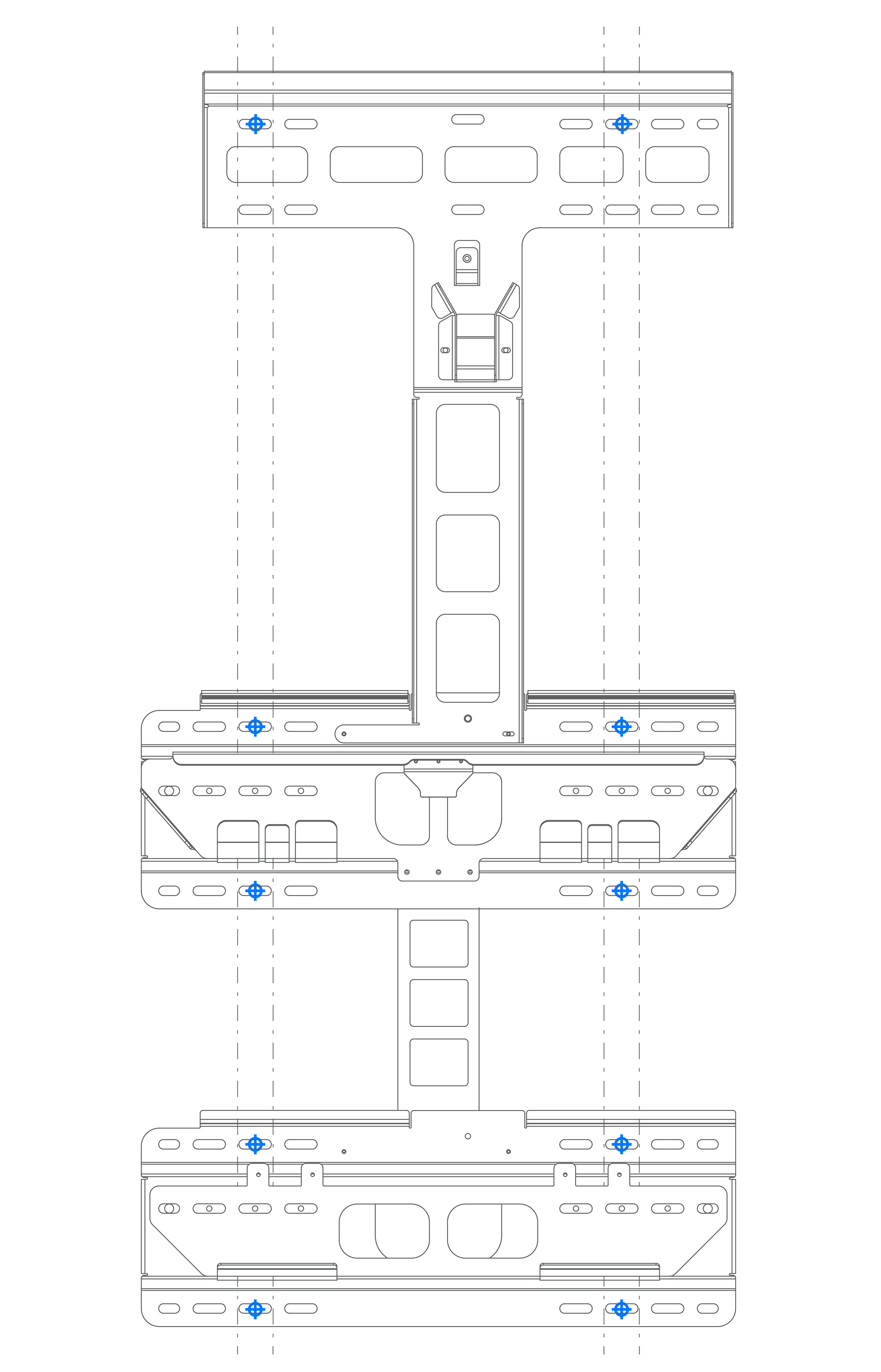
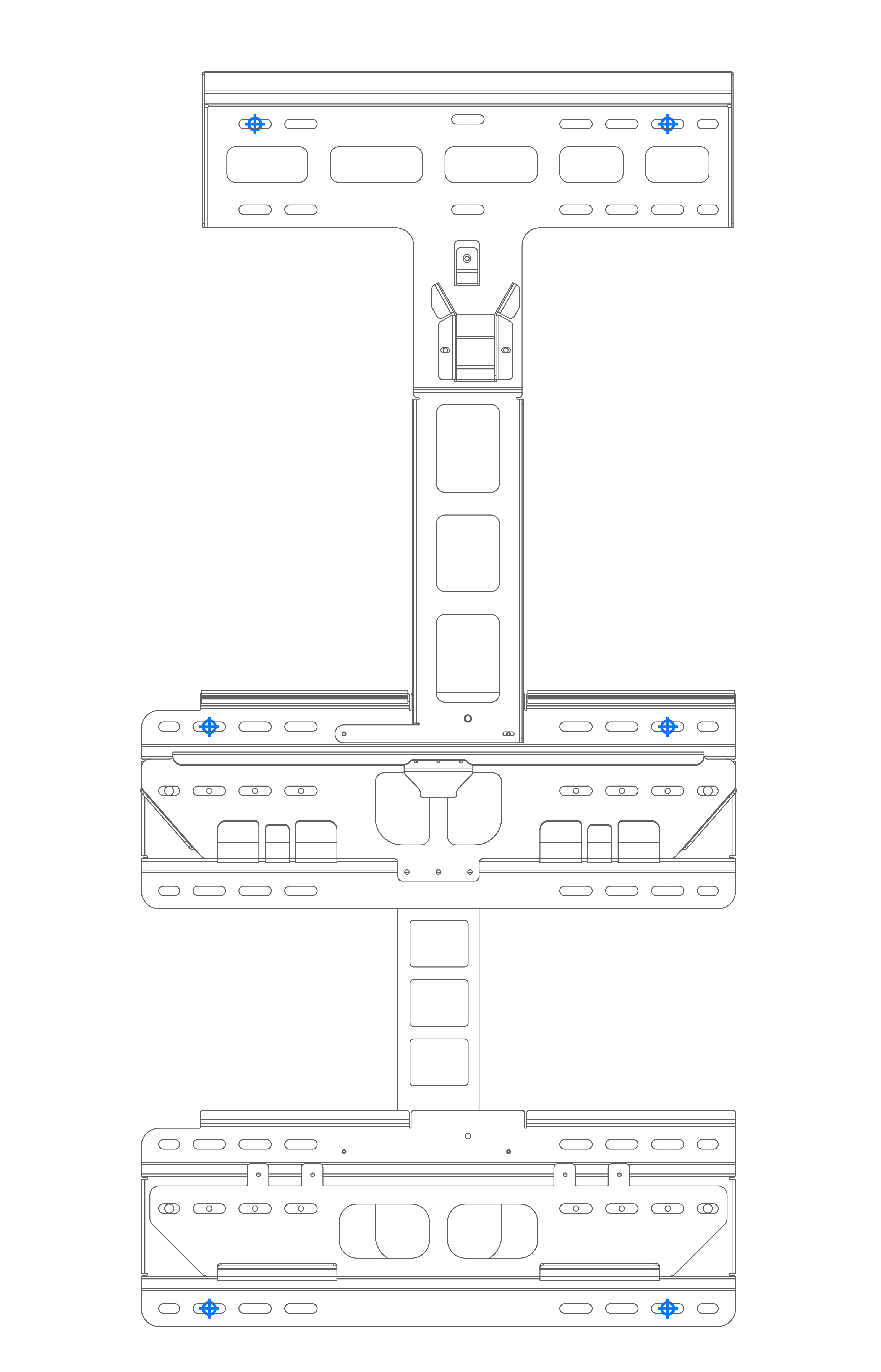
If anchoring directly into wood studs, use at least six (one in each corner, as shown in blue in the diagram on the right) minimum ¼ inch wood screws with washers, of sufficient length for at least 2-½ inch embedment into the studs.

Wood Studs (spaced at 12, 16, 20 or 24 inches)

If anchoring to blocking between wood studs, use minimum 2x4 inch blocks, end-nailed into studs with two 16d nails or toe-nailed into studs with four 8d nails. Use at least six (one in each corner, as shown in blue in the diagram on the right) minimum ¼ inch wood screws with washers, of sufficient length for at least 2-½ inch embedment into the blocking.

A4 - Mounting Bracket Anchoring Details

Metal Studs (spaced at 12, 16, 20 or 24 inches)

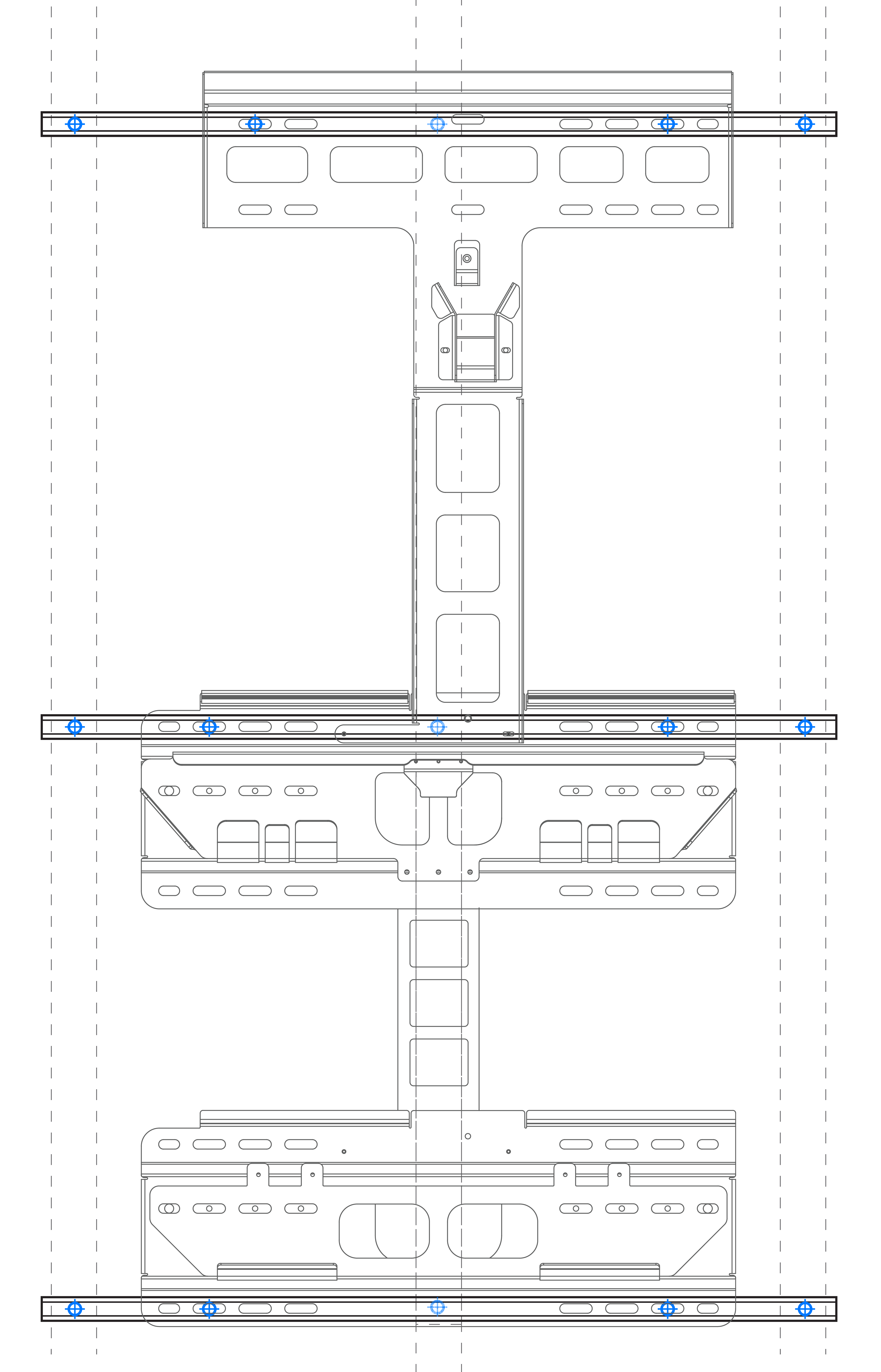
If anchoring directly to metal studs, studs must be minimum 18 gauge. Use at least ten (two in each corner, as shown in blue in the diagram on the right) #14 sheet metal screws with washers, of sufficient length to penetrate at least 3 threads beyond the stud.

Informational PurposesAn informational icon, calling your attention
Note
The solar assembly bracket requires only one anchor on each side.

If backing is needed between the studs, the backing must be minimum 18 gauge. Attach backing to metal studs with 12 gauge 3x3 inch angle clip or Simpson SFC2.25 clips with two #10 sheet metal screws in each leg.

Concrete Masonry Unit Wall

Minimum strength must be 2000 PSI.

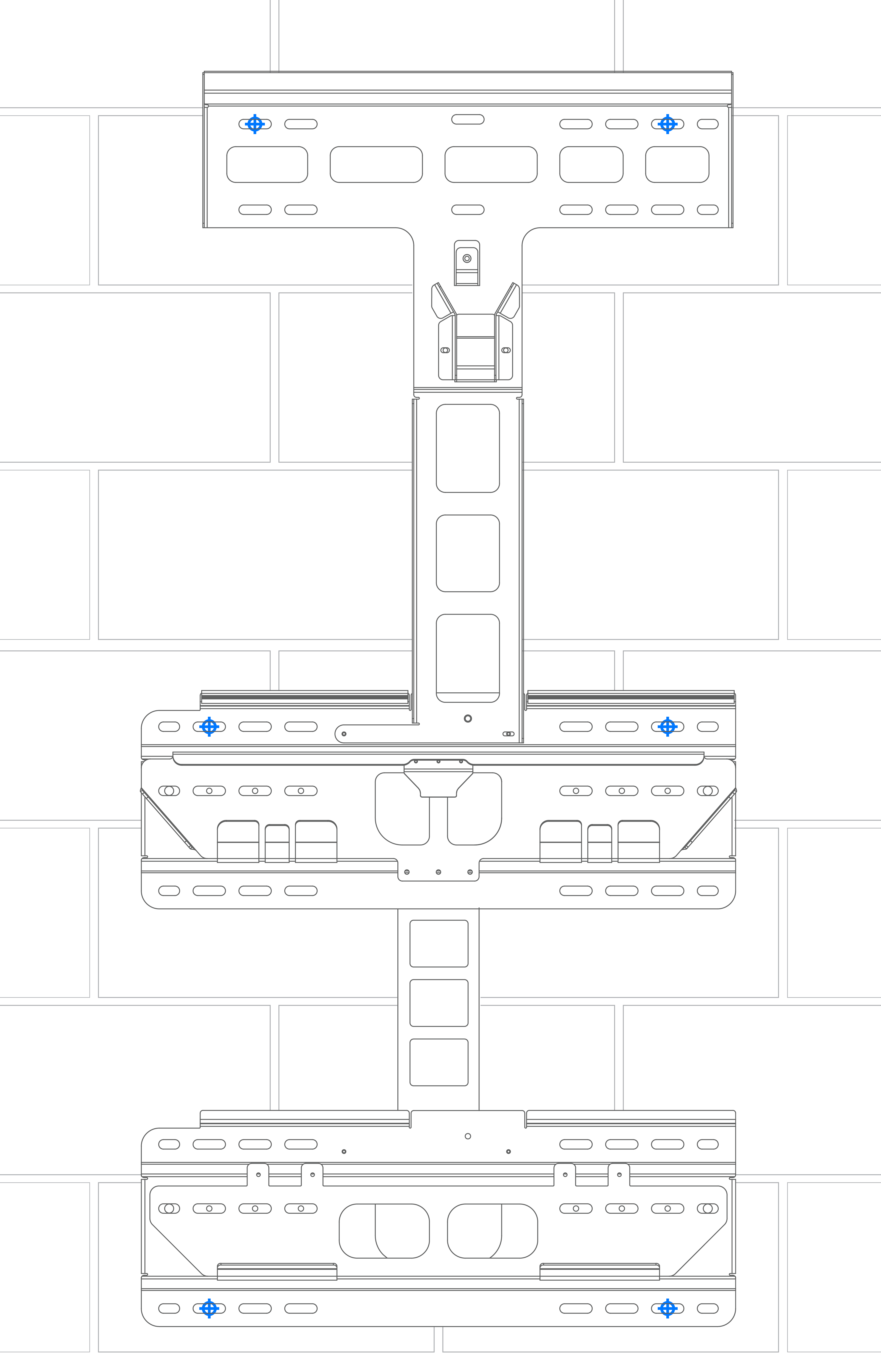
Use at least six (one in each corner, in any available anchor slot) 3/8 inch concrete anchors of sufficient length for the embedment listed below.

Anchors shall not be installed within 12 inches (305 mm) of wall edges or 1-½ inches (38 mm) of masonry block edges.

A5 - Mounting Bracket Anchoring Details

Solid Concrete Wall

Minimum strength must be 2500 PSI.

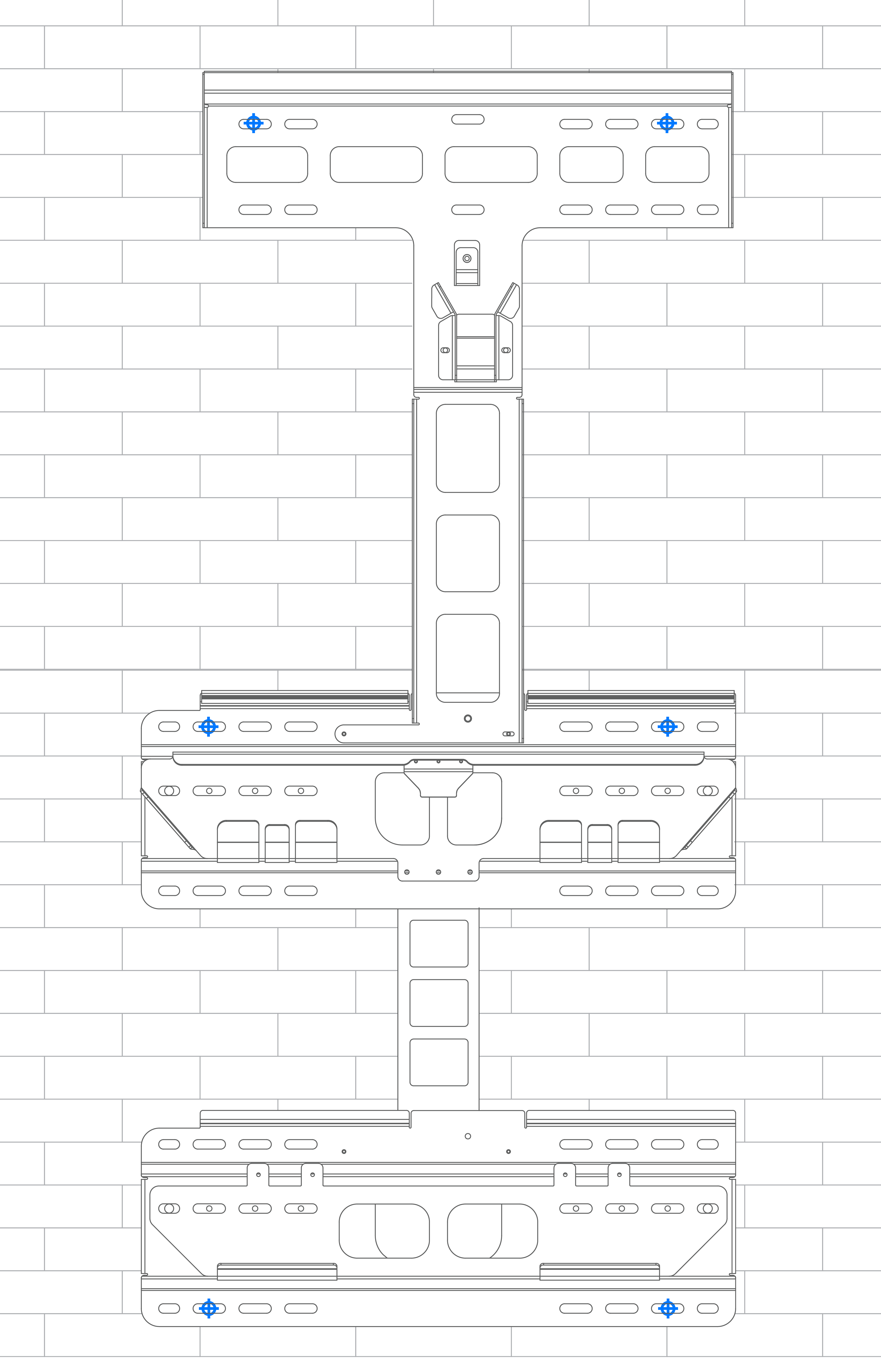
Use at least six (one in each corner, in any available anchor slot) 3/8 inch concrete anchors of sufficient length for at least 2-½ inch (63.5 mm) embedment into the wall.

Brick Wall

(Double and Single Layer of Brick Masonry)

Minimum strength must be 2500 PSI.

Use at least six (one in each corner, in any available anchor slot) ¼ inch masonry anchors of sufficient length for the embedment listed below.

  • Kwik Conn 2 (No ESR). Minimum 1-¾ inch (44.5 mm) embedment required

Brick installation is only permitted in seismic design category A or B, and where ESR anchors are not required. Ground mount only.

Maximum Wind Speed Mounting Location
145 mph Within 10 ft (3048 mm) of wall edge
165 mph Not within 10 ft (3048 mm) of wall edge
Informational PurposesAn informational icon, calling your attention
Note
Faux brick veneer is not a supported wall type for Powerwall installations.
Informational PurposesAn informational icon, calling your attention
Note
Fasteners shall not be installed in mortar joints.

A6 - Mounting Bracket Anchoring Details

Channel Strut (Unistrut)

Struts must be minimum 1-5/8 x 1-5/8 inch, 12 gauge.

If mounting on wood studs, attach each strut to at least three studs, using minimum ¼ inch wood screws with washers of sufficient length for at least 2-½ inch embedment into the studs.

If mounting on metal studs, attach each strut to at least three studs, using at least one #14 sheet metal screw with washer per stud, of sufficient length to penetrate at least 3 threads beyond the studs.

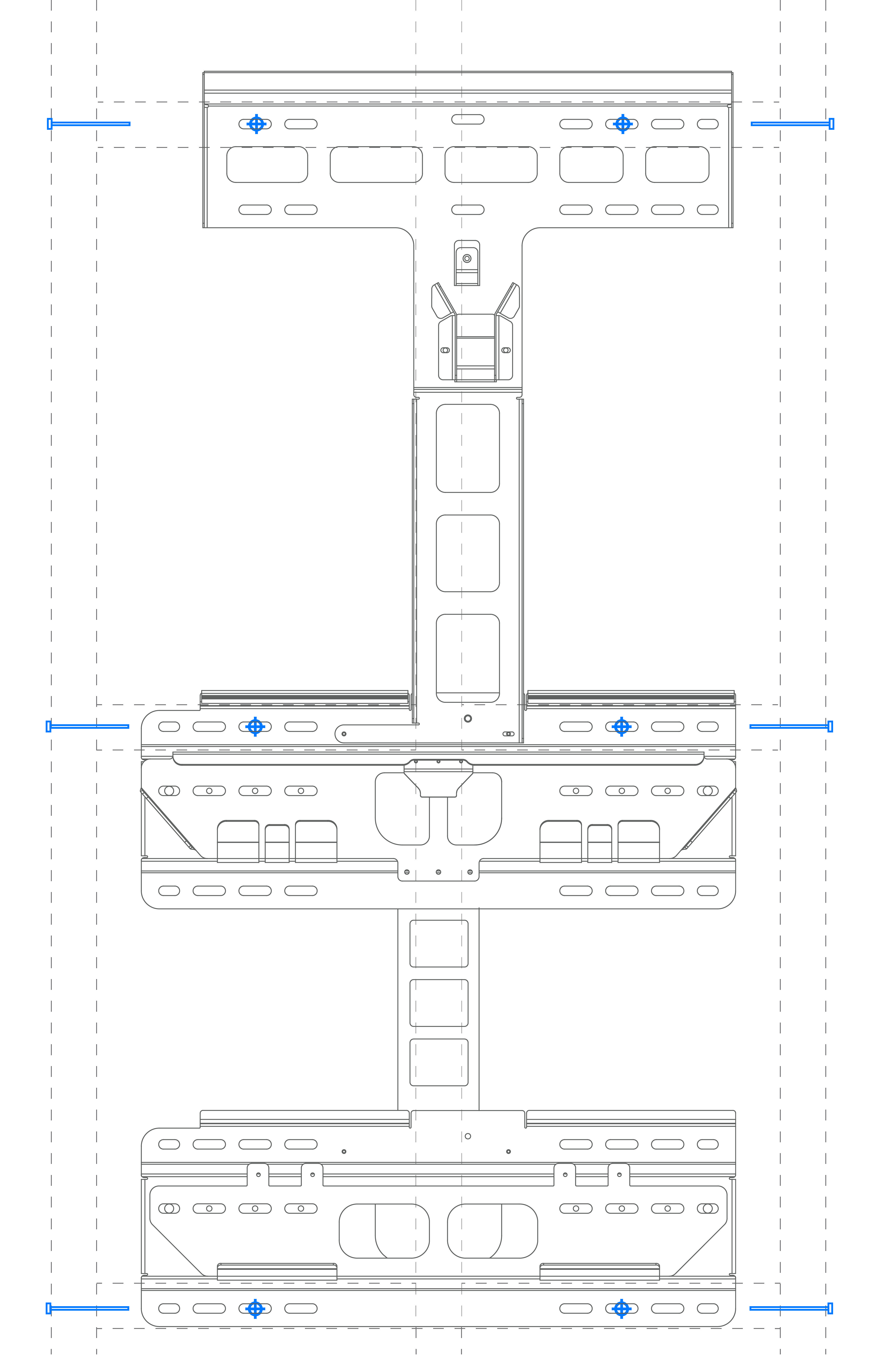
To attach the bracket to the struts, use at least six (one in each corner, as shown in blue in the diagram on the right) ¼ inch hex head screws with washers and strut nuts.

Channel strut shall have a maximum unsupported span of 24 inches (610 mm) and shall not be cantilevered.