STEP 5: Install PV Modules (SKIMBL)
Module drop-in is the same for Portrait orientation as for Landscape. To remember the installation order, think “SKIMBL”: Set Module, Kickstand, Interlock, Manage Wires, Bolt Foot, Level.
-
Set module (SKIMBL).
Position the first module on the tongue side of the front row Leveling Feet. Rock the module down. Forced interference between the Zep Groove of the module frame and the Rockit creates a structural and electrical bond without the need for additional fasteners.
Installation is complete at the Array Skirt.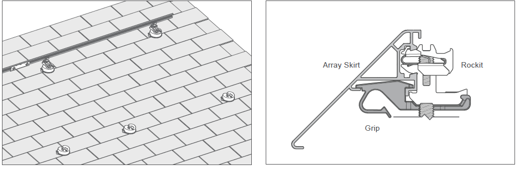 Position module on the tongue side of the front row.
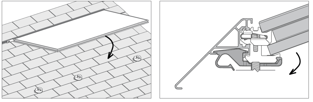 Rock the module down for forced interference.
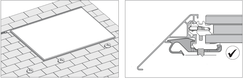
-
Kickstand (SKIMBL).
At the rear edge of the module, install Key side of the Rockit into the Zep Groove of the module frame.
Use the Foot as a “kickstand” to support the module, but do not secure it.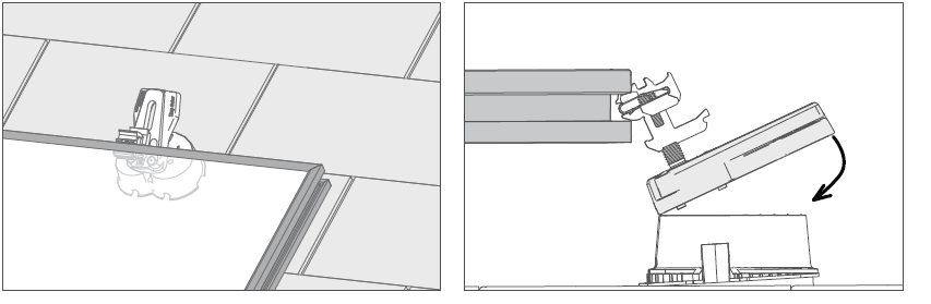
-
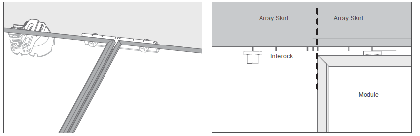
Interlock (SKIMBL).
Install Interlocks between modules. Ensure that the module corner is within the allowable range.
-
Manage wires (SKIMBL).
The DC Wire Clip (Part No. 850-1509) is UL listed to UL 1565 as a Wire Positioning Device.
DC Wire Clip accommodates up to three wires. Refer to Wire Management Recommendations for array wire management.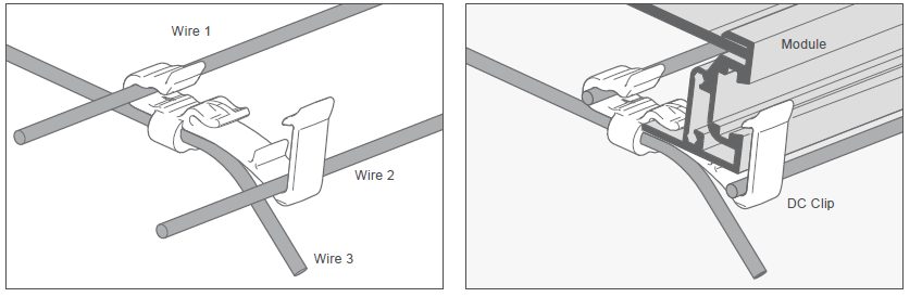
-
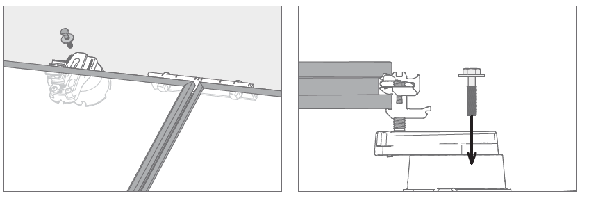
Bolt foot (SKIMBL).
Secure the rear Leveling Feet.
-
Level (SKIMBL).
Uneven leveling is visually apparent, and aesthetically undesirable. Level all the modules so that the array appears to be perfectly flat regardless of roof irregularities underneath. Ensure that first module row is level.
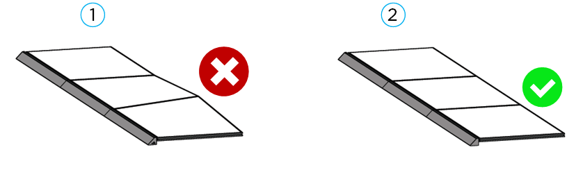
1 - Uneven leveling
2 - Even leveling
Rotate the threaded stud using a #30 Torx bit or Zep Tool to raise or lower module attachment points. (1)
Do not level Rockit beyond 1 1⁄4 inches above the Leveling Foot Base. (2)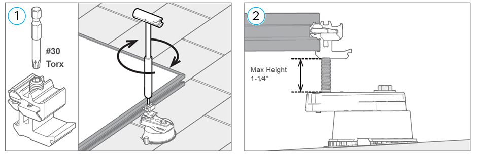
-
Repeat SKIMBL.
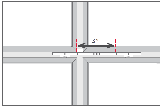
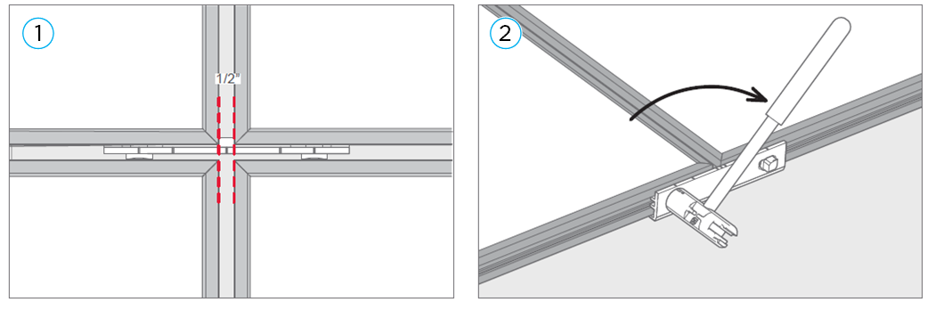
For the second module, align and center the Interlock on module edges. The standard gap between modules is 1/2 inch (1) with a total range of 3 inch (in case of inteference with the Leveling Foot). Use the Zep Tool to turn Interlock Zeps from position 1 to postion 3 (2). Tongue side of Interlock allows flexibility for small variations in module sizes. Allowable gap is still structurally electrically bonded. The farthest allowable position to align with module edge when shifting Interlock is shown below. Continue to install Modules, Leveling Feet and Interlocks until the array is complete. Be sure to “SKIMBL” every row.
 Tongue of Interlock allows for some flexibility.
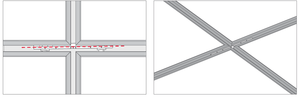 Maximum range is indicated on Interlock.