Appendix D: Thermal Expansion
There are two methods to address thermal expansion and contraction within Tesla Zep Compatible™ arrays: Thermal Expansion Joints and physical gaps or breaks between sub-arrays.
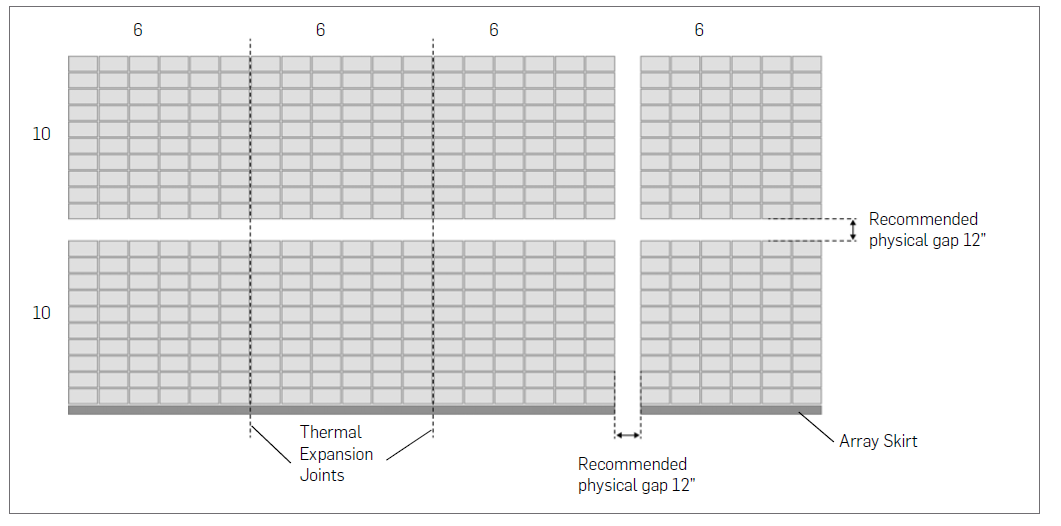
Thermal Expansion Joints consist of Interlocks that are installed in a manner that allows modules to slide back and forth as they expand and contract in response to daily temperature swings on the roof. This allows the modules some added flexibility to expand in the direction that the Interlocks are running. In the other direction (North-South in the case of ZS Span), a physical gap is required to allow for thermal expansion of the modules. Generally, a gap of at least 12” between sub-arrays is recommended, both for thermal expansion and to allow access by work crews for module servicing.
When are thermal expansion joints needed?
- Array sizes larger than 10 meters or approximately 33 feet in either direction.
- After two consecutive Thermal Expansion Joints, a physical gap is required.
Installing Thermal Expansion Joints
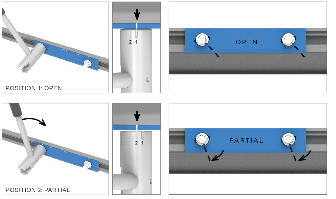
Thermal Expansion Joints use the Interlock component, which is used to connect and bond two modules together. To create a Thermal Expansion Joint between two modules, rotate the Interlock Zep on one side to Position 3 (locked position) using the Zep Tool. Rotate the Interlock Zep on the other side to Position 2. Position 2 provides a structural connection, but does not establish an electrical bond. This allows the module on the side of Position 2 to slide back and forth as the modules expand and contract in changing temperatures.
Thermal Expansion Joints and Module Columns
When there is a continuous column of Interlocks all serving as a thermal expansion joint, all Interlocks must be tightened consistently going up the column. In most cases, one side is turned to Position 3, and the other side to Position 2, the exception being a staggered array. For example, a North-South drop-in with thermal expansions that run East-West could be installed as follows:
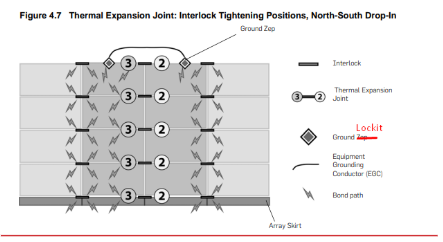
Thermal Expansion Joint: Interlock Tightening Positions, North-South Drop-In
Physical Gaps Between Sub-Arrays
Thermal Expansion Joints only work along the axis of the Interlock. Thermal expansions running along the other axis (parallel to the module drop-in direction) require a physical break between the sub-arrays. For example, a vertical North-South drop-in may require physical breaks between rows.
At a minimum, the gap should be at least 4 inches or 100 mm. However, a gap of 12 inches or 300 mm is recommended for ease of servicing.
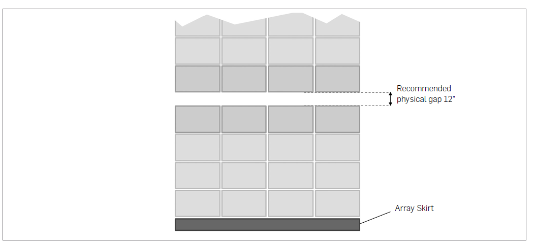
North-South Drop-In, North-South Thermal Expansion Gap
North-South Drop-In, North-South Thermal Expansion East-West
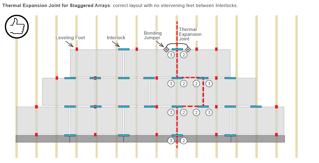
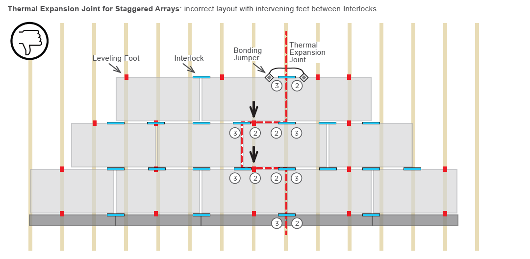
Thermal Expansion Joints in Staggered Arrays
When module rows are offset from one another, creating a Thermal Expansion Joint is more complex, requiring additional Interlocks and a continuous path between them with no intervening Feet.
Thermal Expansion Joints on staggered arrays require Interlocks at each juncture where the array is intended to split apart. Each Interlock Zep is turned to Position 2 on one side (allows thermal expansion) and Position 3 (fully locked in place) on the other such that there is an unbroken line between the Zeps that are at Position 2. The installer must not place any Leveling Feet or Cam Feet between these points.