STEP 7: Install PV Modules
-
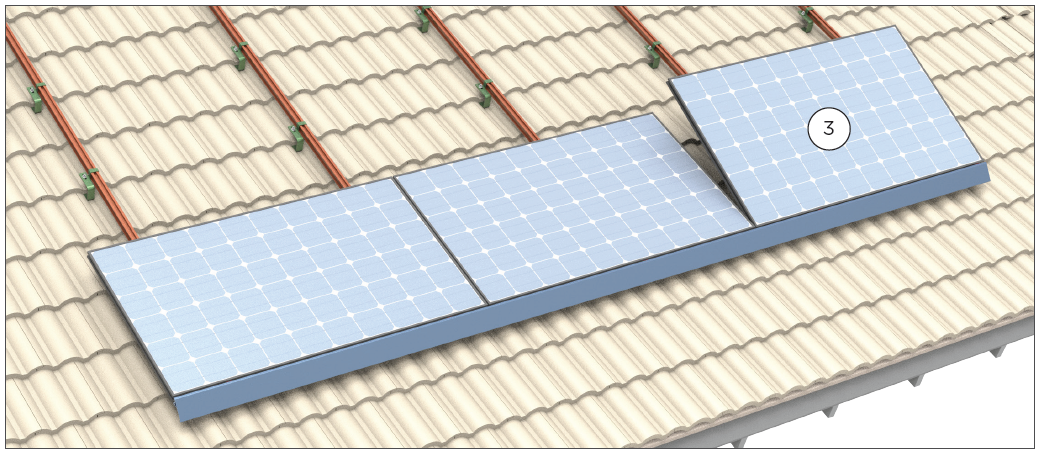
Drop in first module.
Position the first module on the tongue side of the front row Cam Feet (1A). Rotate module downward almost flat, while pushing module onto tongues of Cam Feet and Interlocks (1B). Frame engages at 15 degrees. If needed, lift module up slightly, and apply force towards Cam Feet to seat the module completely.
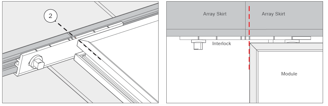
Installation is complete at the Array Skirt.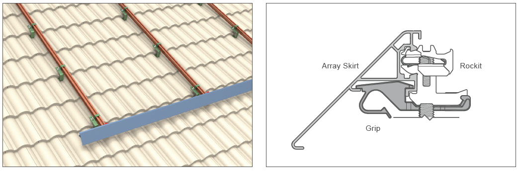 Position module on the tongue side of the front row.
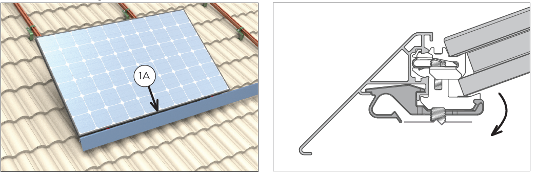 Rock the module down for forced interference.
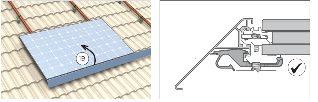
-
Align to Interlock.
Ensure that the module corner aligns with the outer timing mark on the Interlock.
-
Drop in the remaining modules in the first row.
-
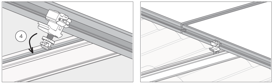
Install rear Cam Feet in the first row.
Manually insert the Key side of the Cam Foot into Zep Groove while aligning Cam Foot base with Spanner Bar channel. Flat face of Rockit should be flush with module frame.
-
Install the rear Interlocks in the first row.
Align the Interlocks with module corners using timing marks.
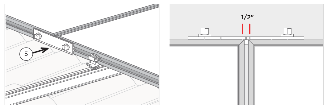 The Interlock can slide to one side if needed, to avoid conflicting with a nearby Cam Foot. The module must remain within the marks for allowable position. Total range is 3” or 76mm. If the Key side of an Interlock Zep is visible, the Interlock is positioned too far to one side.
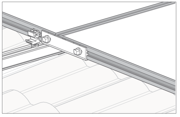
Conflict with Cam Foot
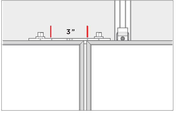
The module must remain within these marks.
-
Level Cam Feet.
Uneven leveling is visually apparent, and aesthetically undesirable. Level all the modules so that the array appears to be perfectly flat regardless of roof irregularities underneath. Ensure that all modules in first column are level. This will aid in keeping the rest of the array true.
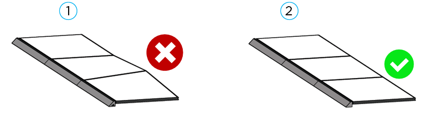
1 - Uneven leveling
2 - Even leveling
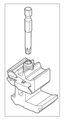
Rotate the threaded stud using a #30 Torx bit or Zep Tool to raise or lower module attachment points. Do not level Rockit beyond 1 ¼ inches above the Cam Nut.