STEP 1: Layout and Preparation
Compare projected rafter locations on the project plan set with actual rafter locations; ensure that the layout is accurate. Create a chalk layout on roof according to the project plan set, then mark the locations of Base Feet.
Refer to the project plan set for Engineering Rules regarding maxumum spacing, cantilever, and fire setbacks.
Example project plan set:
Maximum span, cantilever, and cross bracing locations are project-specific values that depend on factors such as wind zone, snow load, and neighborhood topography. Check the project plan set for these values. If project-specific values are not available, you can refer to these system-wide rules that apply to all ZS Ramp systems regardless of project conditions.
- Tilt range is 0-15 degrees.
- The system can be installed in either Landscape or Portrait orientations.
- Spans can never exceed 72 inches in the East-West or North-South direction.
- Module or rail cantilever can never exceed 24 inches.
- Cam Foot minimum distance from a module corner is 2 inches, measured from the center of the Cam Foot threaded stud.
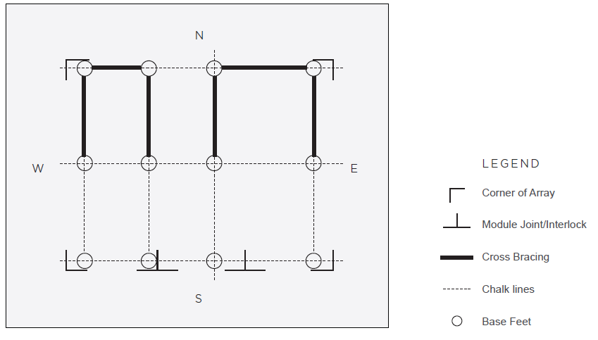
- When required, North-South Cross Bracing will ALWAYS span the shortest and outermost Tube Assemblies.
- When required, East-West Cross Bracing will ALWAYS span the backmost and outermost Tube Assemblies.
- Cross bracing will occur between 5 and 15 degrees.