Rapid Shutdown (RSD) E-Stop Test Failed
When performing the E-Stop test to confirm Rapid Shutdown (RSD) wiring is correct on a Powerwall+, the test fails and RSD does not initiate.
Note
For Powerwall+ units on software version 24.4.2 or
greater, failing the RSD Self Test five times in a row will result in RSD Self Test
Lockout, causing the unit to go to sleep. If this has occurred:
- Disconnect the E-Stop button wiring and replace the Rapid Shutdown (RSD) jumper.
- Turn the Powerwall+ switch OFF, wait 3 seconds, the turn the switch ON.
- Wait for the Powerwall+ LED to blink red, then turn the Powerwall+ switch OFF, wait 3 seconds, and turn the switch back ON.
- Confirm the System Shutdown Switch Emergency Stop (E-Stop) button is in the engaged (pushed in) position.
- Disconnect the E-Stop button
wiring and replace the Rapid Shutdown (RSD) jumper. Turn the Powerwall+ Enable switch OFF.
Figure 1. Powerwall+ RSD Jumper  NoteAlthough the Enable switch is NOT a certified means of Rapid Shutdown (RSD) per NEC 690.12 for Powerwall+, turning the Enable switch off will shut down all equipment.
 - If turning the Enable switch off
DOES shut down all equipment,
reconnect the E-Stop button wiring and inspect the following:
- Confirm the RSD jumper
has been removed and the E-Stop button is connected to the RSD IN / RSD
Out ports.
- Confirm the RSD connector is not damaged; if the connector is broken or compromised and cannot be fixed, contact Install Support.
- Confirm the wires are free of damage and the lines present proper continuity. If any damaged wiring is found, replace it.
- Confirm the wires have been stripped sufficiently to make contact with the connector.
- Confirm the wires are securely terminated and all terminals have been torqued correctly.
- Confirm the terminal block is seated correctly on the E-Stop DIN rail.
- Perform a continuity test on the RSD wires at the Powerwall+; the tester should ring when touching the RSD wires, and should stop ringing when the E-Stop is engaged.
- If there are multiple Powerwall+ units, confirm each
unit is connected to a dedicated electrical contact of the E-Stop.NoteThe following illustrations depict Powerwall 3, but the concepts are applicable to Powerwall+ as well.
Figure 2. Good Wiring Example: Each Unit Connected to Electrical Contact in E-Stop 
Figure 3. Bad Wiring Example: Both Powerwall 3 Connected to a Single Electrical Contact 
Figure 4. Bad Wiring Example: Powerwall 3 Units Connected to E-Stop in Series (Does Not Work) 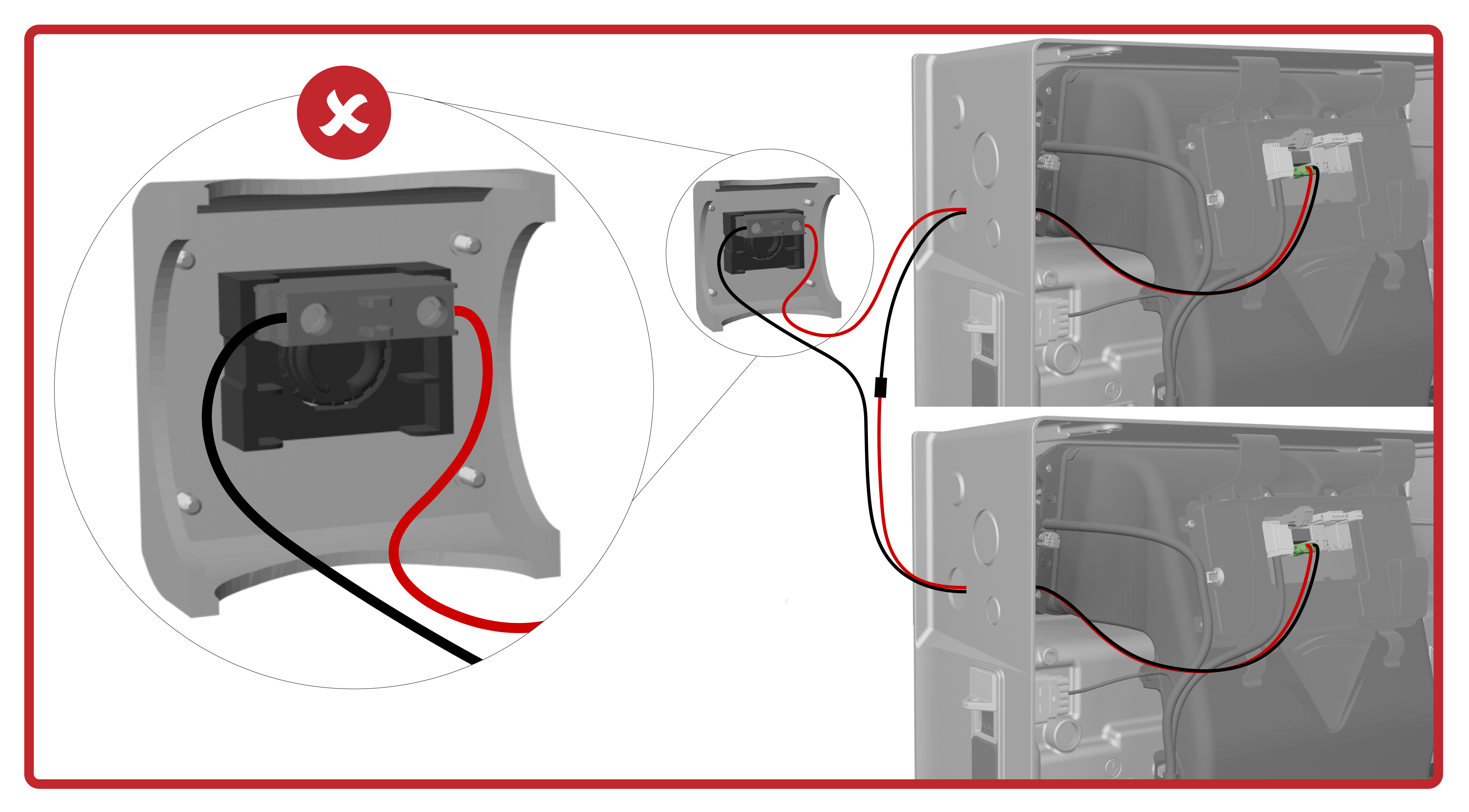
Figure 5. Bad Wiring Example: Second Powerwall 3 Not Connected to E-Stop 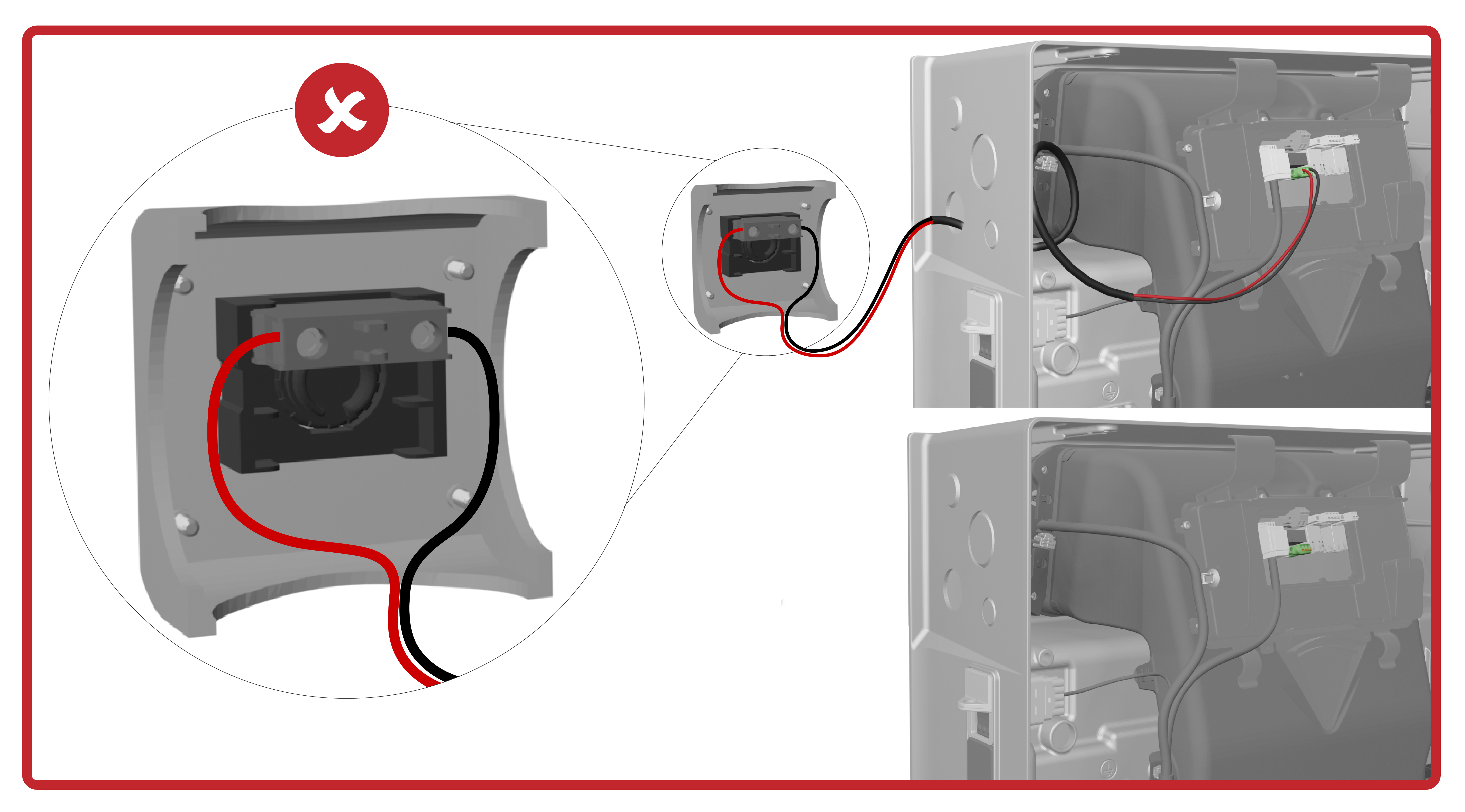
- Confirm the RSD jumper
has been removed and the E-Stop button is connected to the RSD IN / RSD
Out ports.
- If turning the Enable switch off
DOES NOT shut down all equipment:
- Inspect the Rapid Shutdown wiring
harness in the Powerwall+ battery assembly:
- Ensure the Rapid
Shutdown wiring harness is not disconnected.
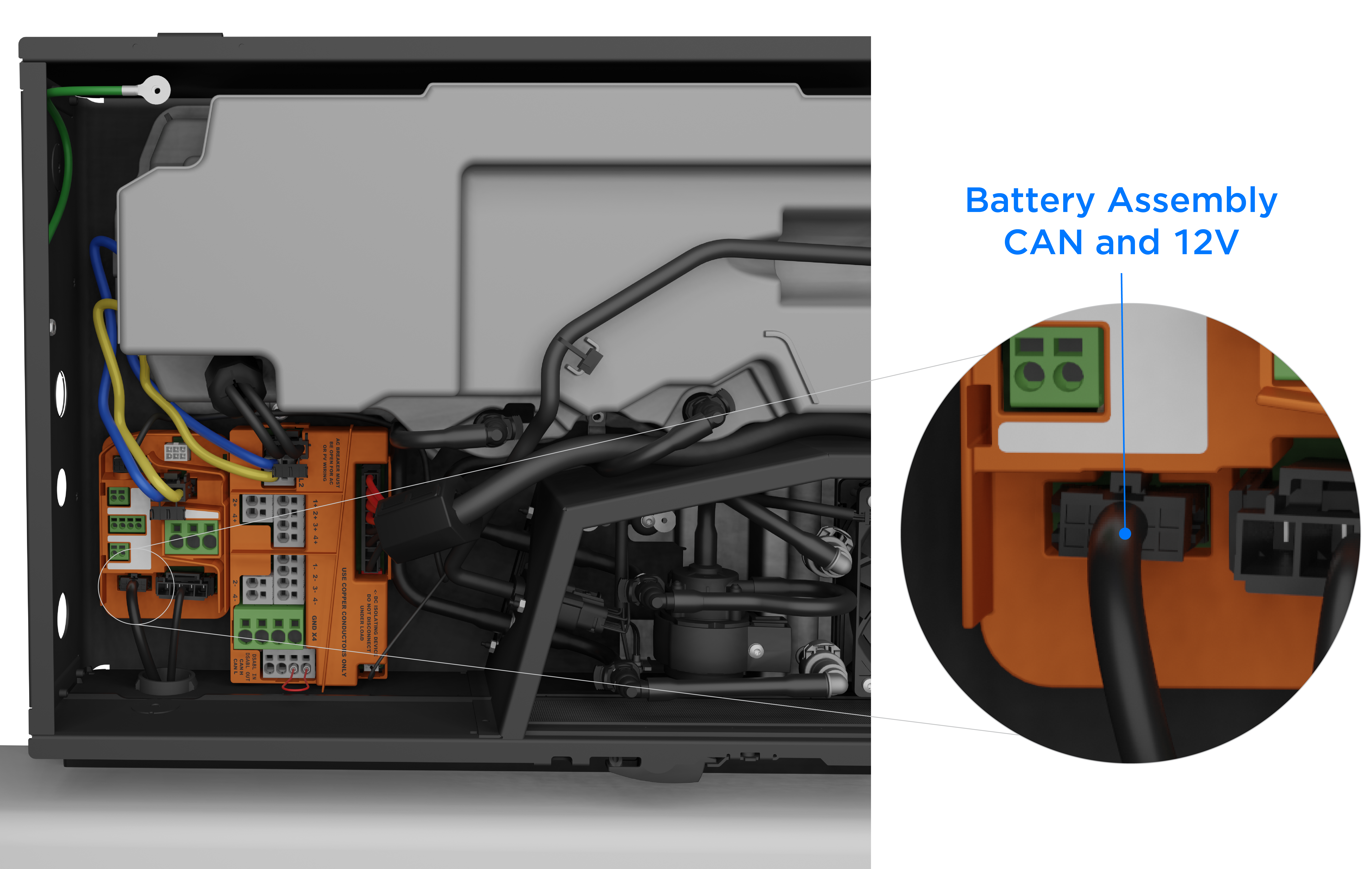
- Disconnect the
Rapid Shutdown wiring harness and measure the voltage between
the two terminals of the connector (at the ends of the blue and
white wires). If the value is not stable and close to 12V,
ensure the battery assembly CAN and 12V connector is securely
plugged in to the terminal in the solar assembly. If the voltage
reading is still 0V, replace the battery assembly CAN and 12V
harness as it may have been damaged.
- At the Rapid Shutdown wiring harness, measure the continuity between the two pins at the ends of the red and black wires. If there is no damage to the harness, the pins will be shorted when the Enable switch is ON.
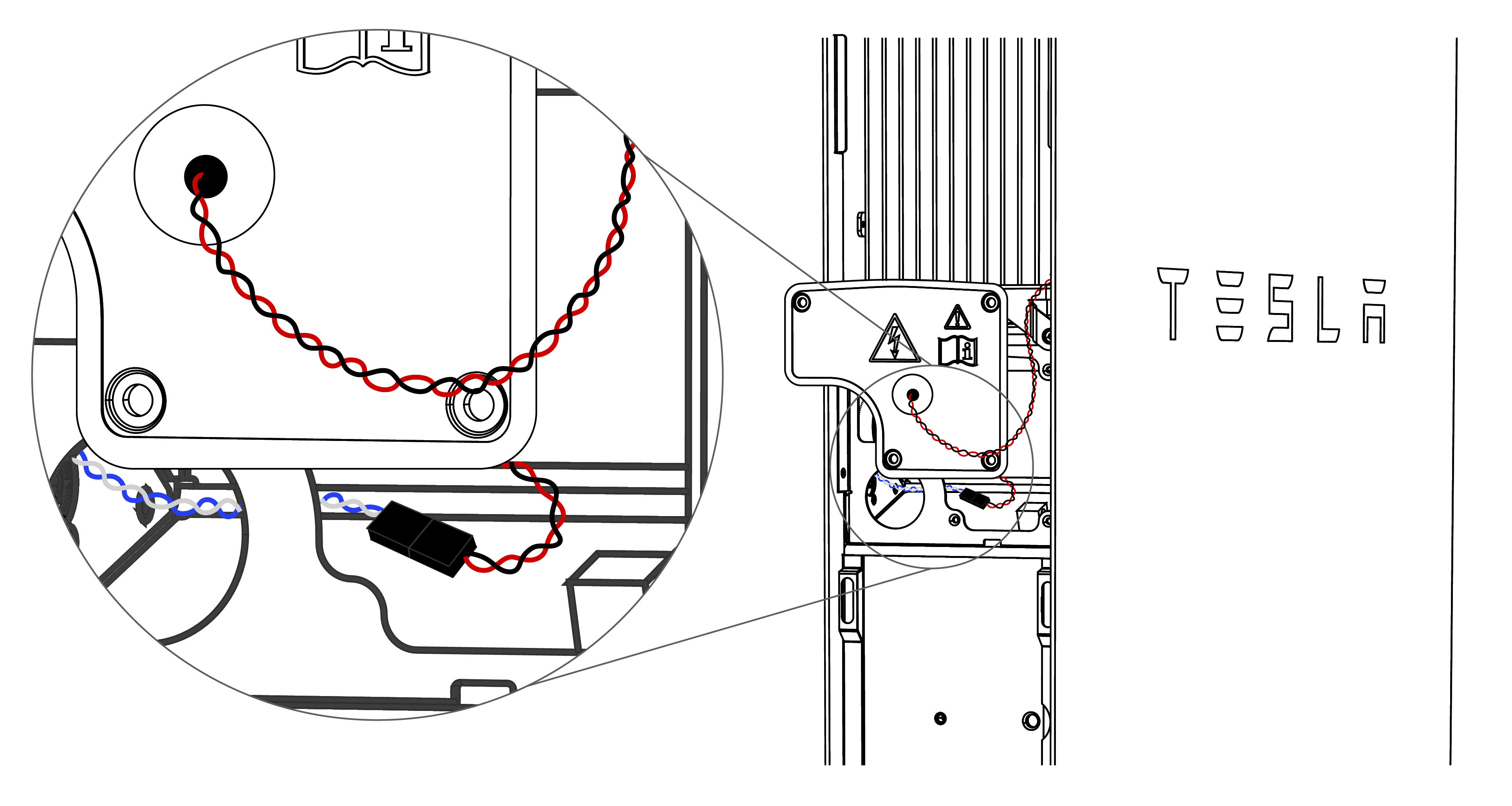
- If the harness is
damaged, splice the wires and use connectors to repair it.WarningTurn the Powerwall+ Enable switch OFF, then turn the Powerwall+ breaker OFF before cutting any wires.
Figure 6. Rapid Shutdown Wiring Harness Spliced with Wagos 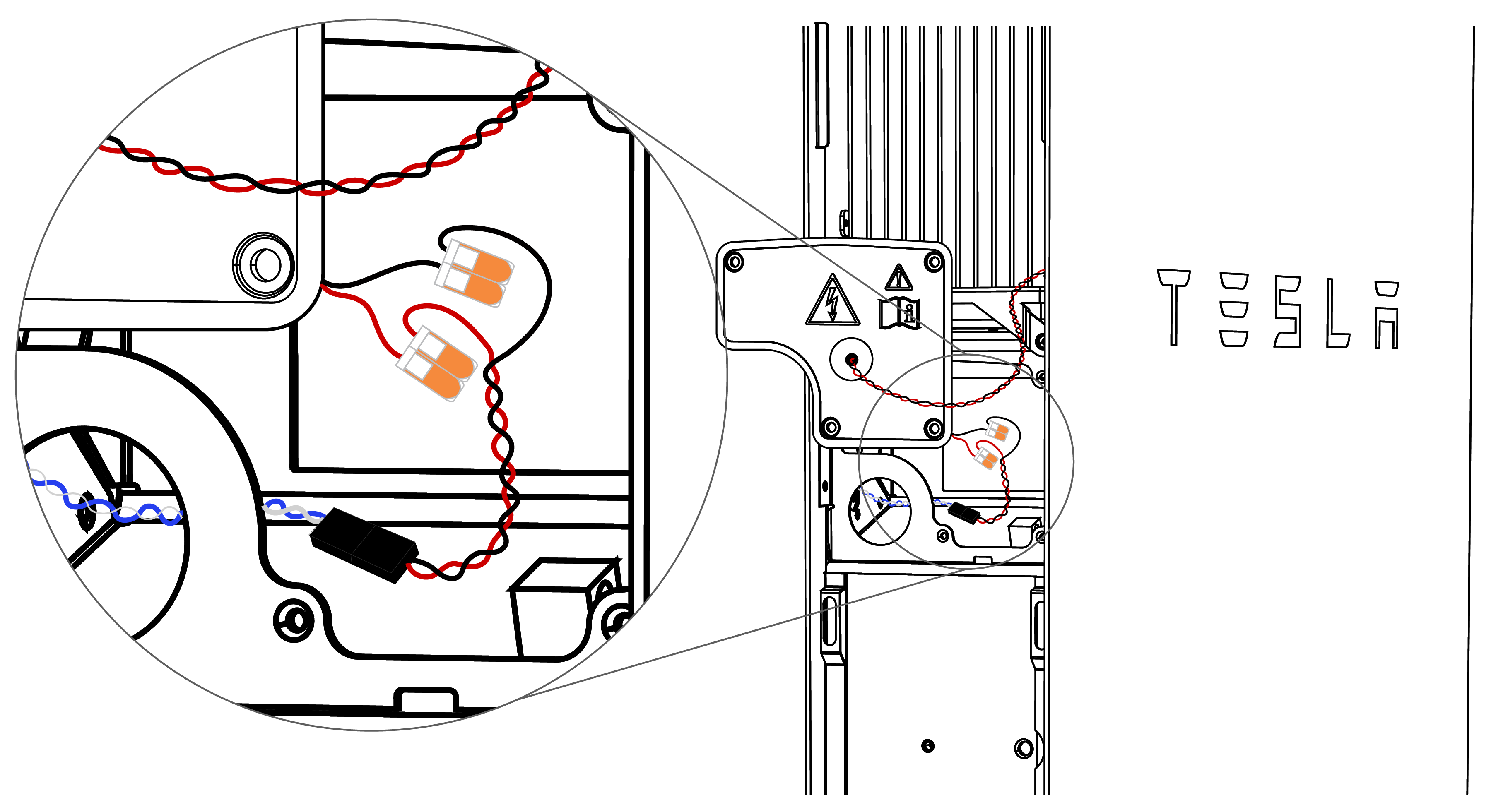
- Ensure the Rapid
Shutdown wiring harness is not disconnected.
- If RSD still fails to initiate, contact Tesla Install Support.
- Inspect the Rapid Shutdown wiring
harness in the Powerwall+ battery assembly: