Powerwall+ / Tesla Solar Inverter Rapid Shutdown (RSD) Initiated
Symptoms
On the landing page, the following alert appears under the Powerwall+ / Tesla Solar Inverter: "Rapid Shutdown Initiated. Check AC breaker and low-voltage rapid shutdown circuit".
Warning
Only an Electrically Qualified Person is to perform these
troubleshooting steps.
Warning
This procedure includes steps to measure voltage across terminals
with breakers closed, meaning conductors are under load. Never unplug conductors
that are under load.
Steps to Troubleshoot
Note
It takes approximately 30 seconds to move out of the RSD triggered state; allow at
least 30 seconds after each troubleshooting step to see if the alert has been
cleared.
- For Powerwall+ units, ensure the Enable switch is ON.
- Ensure the Rapid Shutdown (RSD)
jumper is in place for each Powerwall+, and the Gateway if present
(remove System Shutdown Switch if present and reinstall RSD jumper to simplify
troubleshooting).
Figure 1. Powerwall+ RSD Jumper 
- If there are multiple Powerwall+ units installed, perform
the following steps to determine which unit is triggering RSD:
- Using a multimeter,
measure the voltage between the RSD IN pin and a GND pin. The value
should be approximately 12V.
- If the voltage measurement is 0, this unit is triggering RSD.
- Using a multimeter,
measure the voltage between the RSD IN pin and a GND pin. The value
should be approximately 12V.
- For the unit triggering RSD:
- Remove the RSD jumper and
use the multimeter to measure the voltage across the two RSD pins. The
value should be approximately 12V; if it reads 12V, reinsert the RSD
jumper and wait 30 seconds to see if the alert is cleared.NoteIf the value is oscillating between 0V and 12V every second, please contact Install Hotline.
- If the system has a System Shutdown Switch, perform a continuity test on the 12V and GND wires coming from the switch. If the circuit is not continuous, inspect the wiring.
- Using a multimeter,
measure the voltage between L1 and L2 in the solar assembly AC wiring
harness. The value should be approximately 240V; if it is 0V, ensure the
connector plugged into the Powerwall+ communication board
is fully seated. If the measurement is still 0V, please contact Install
Hotline.
- Using a multimeter,
measure the voltage between L1 and L2 in Powerwall+ AC terminals. The
value should be approximately 240V; if it is 0V please contact Install
Hotline.
- Inspect the Rapid
Shutdown wiring harness in the Powerwall+ battery assembly:
- Ensure the Rapid
Shutdown wiring harness is not disconnected.
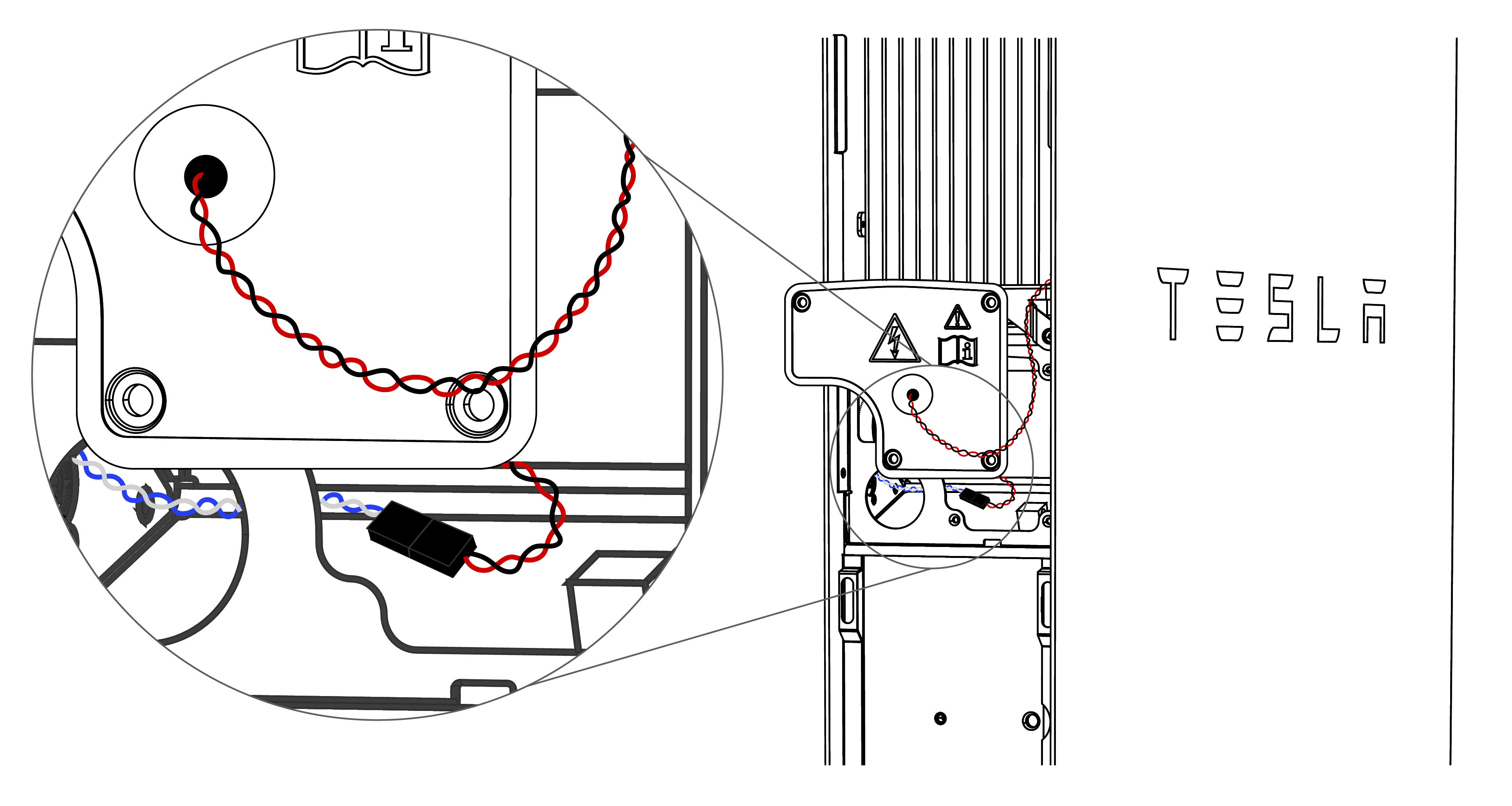
- Disconnect the
Rapid Shutdown wiring harness and measure the voltage between
the two terminals of the connector (at the ends of the blue and
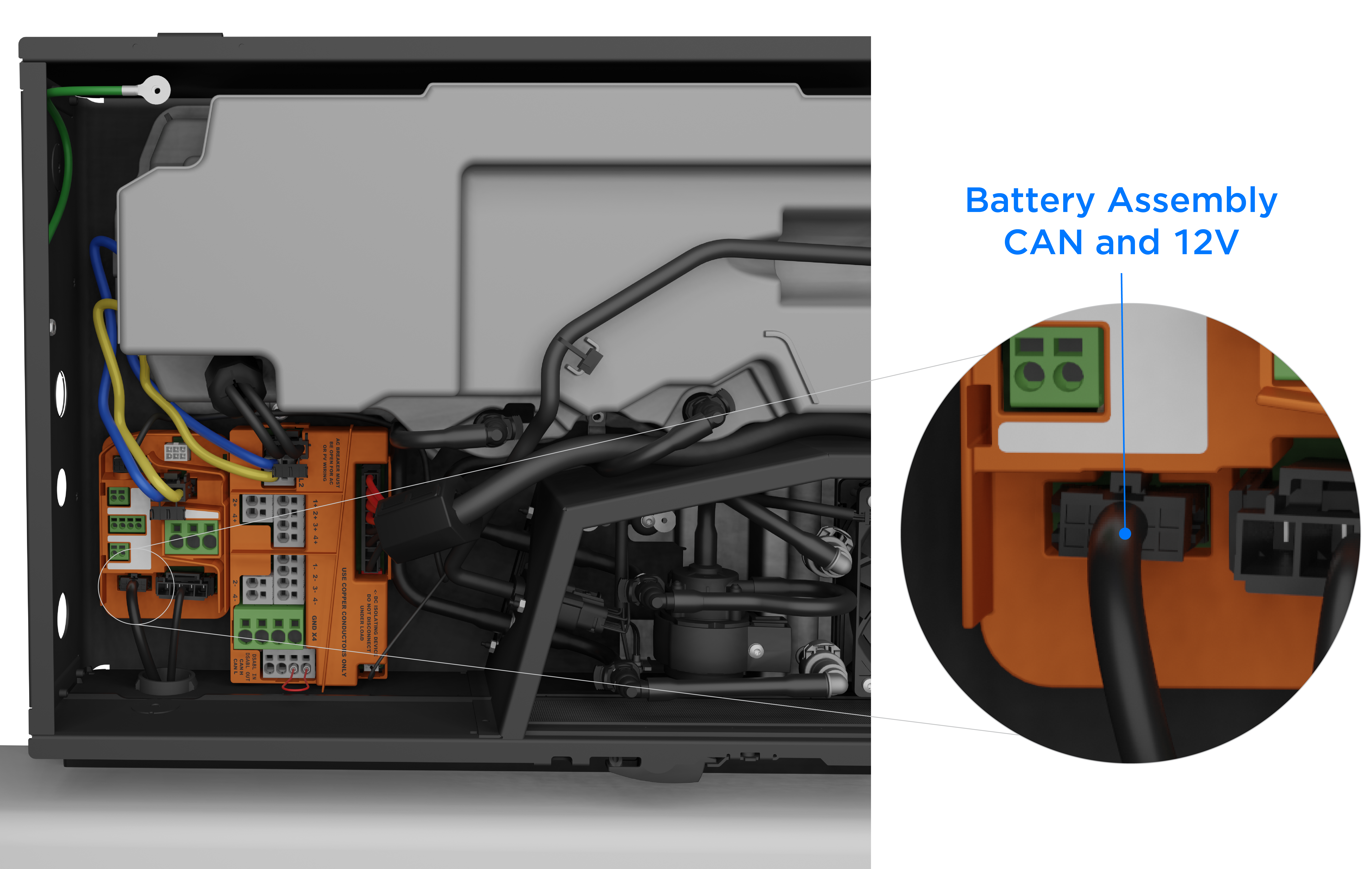
white wires). If the value is not stable and close to 12V,
ensure the battery assembly CAN and 12V connector is securely
plugged in to the terminal in the solar assembly. If the voltage
reading is still 0V, replace the battery assembly CAN and 12V
harness as it may have been damaged.
- At the Rapid Shutdown wiring harness, measure the continuity between the two pins at the ends of the red and black wires. If there is no damage to the harness, the pins will be shorted when the Enable switch is ON.
- If the harness is
damaged, splice the wires and use connectors to repair it.WarningTurn the Powerwall+ Enable switch OFF, then turn the Powerwall+ breaker OFF before cutting any wires.
Figure 2. Rapid Shutdown Wiring Harness Spliced with Wagos 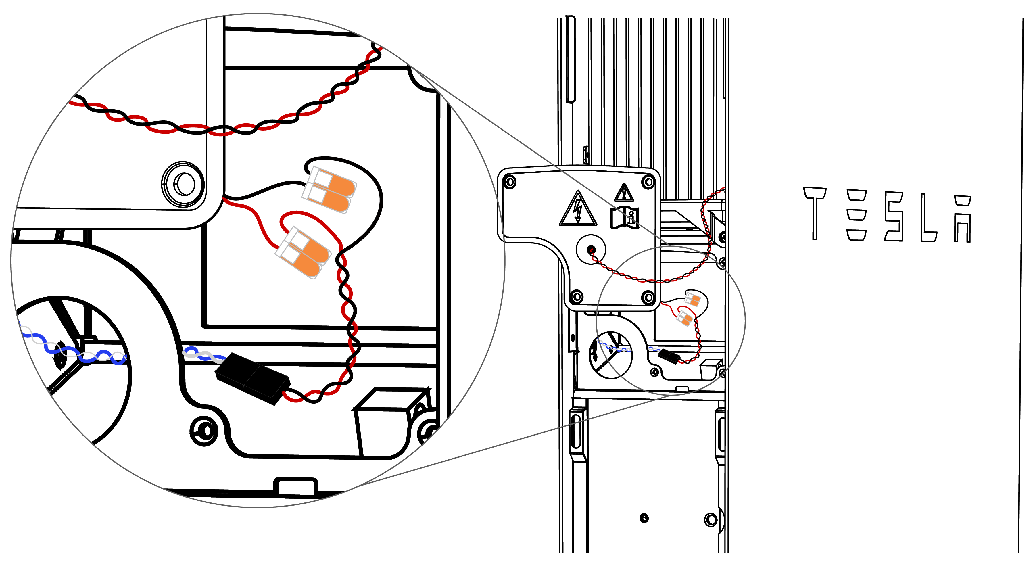
- Ensure the Rapid
Shutdown wiring harness is not disconnected.
- Remove the RSD jumper and
use the multimeter to measure the voltage across the two RSD pins. The
value should be approximately 12V; if it reads 12V, reinsert the RSD
jumper and wait 30 seconds to see if the alert is cleared.