Negative Solar Reading
On the landing page, the Solar value is negative and does not match the solar production reading from the inverter
Symptoms
On the landing page, the solar value is negative and does not match the solar
production reading from the inverter.
Note
For
multi-product installations, see Negative Loads Alert for Multi-Product Installation.
Note
To troubleshoot this issue, measure solar production
using one of the following methods:
- For Tesla Solar Inverter,
use the Solar Inverter Configuration Interface or measure with a multimeter
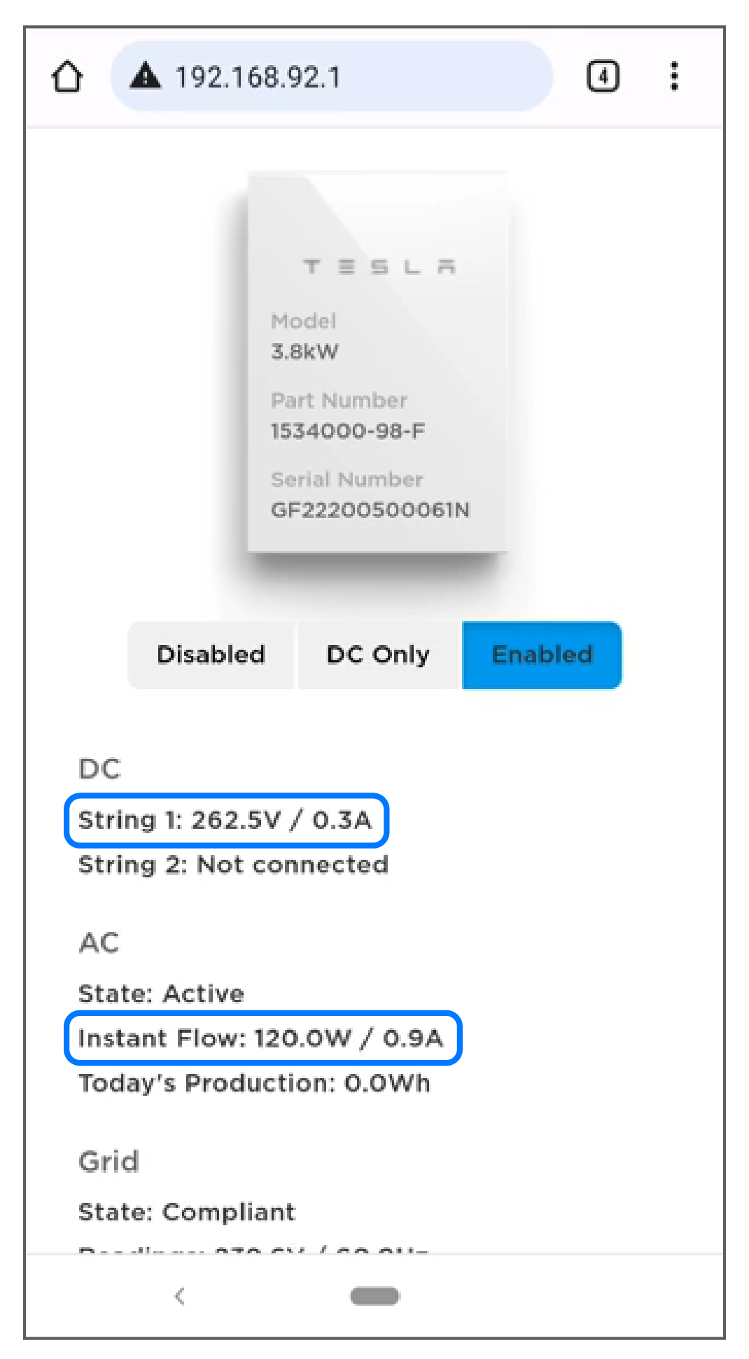
- For a third party inverter, use the display on the inverter itself (if present), the inverter production monitoring app, or measure with a multimeter
Steps to Troubleshoot
- Confirm the CT is facing the correct way:
- Locate the CT(s) used to measure the source that is displaying incorrect power flow readings.
- Verify the CT(s) are oriented such
that the label is facing toward the source (away from the breaker).
- Solar Current Transformer: Label toward the inverter
- Site Current Transformer:
Label toward the Grid
Figure 1. Tesla 100 A CT (for Backup Gateway 2) Orientation in Relation to Power Flow 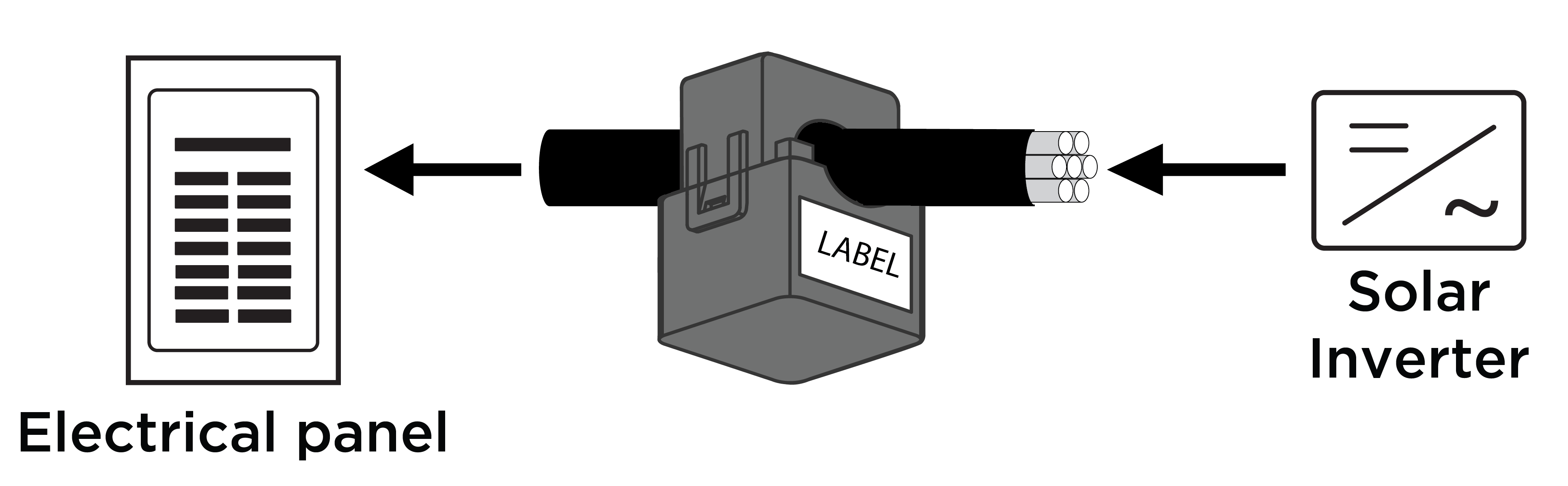
Figure 2. Neurio W2 CT Correctly Oriented to Measure Solar (top) and Incorrectly Oriented (bottom) 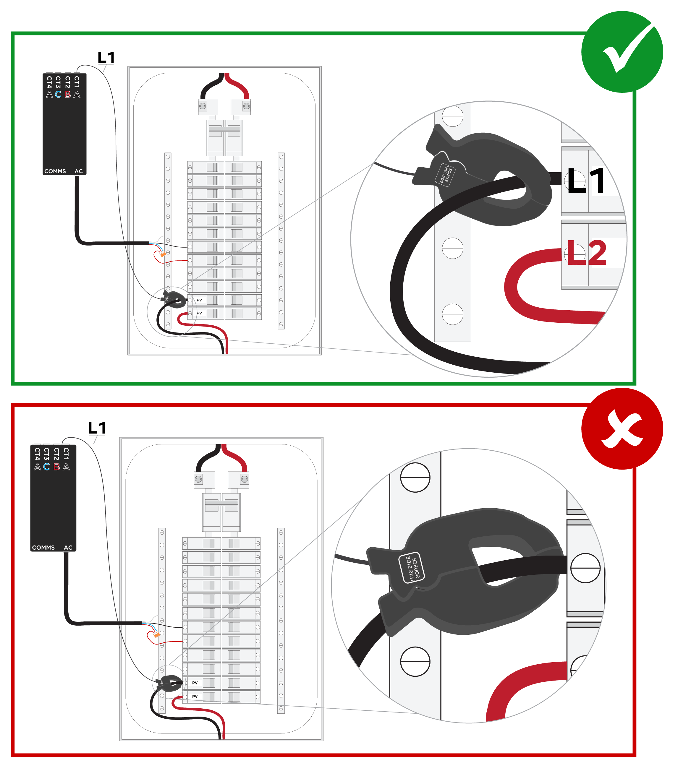
- Confirm the CT is measuring the correct phase:
- Locate the CT on the Meter page in the Device Setup interface in Tesla One.
- Determine which phase the CT should
be measuring.
- Backup Gateway 2 with
Tesla 100 A CTs:
CT1 Line 1 CT2 Line 2 CT3 Defaults to Line 1 but can be configured as Line 2 during device setup in Tesla One 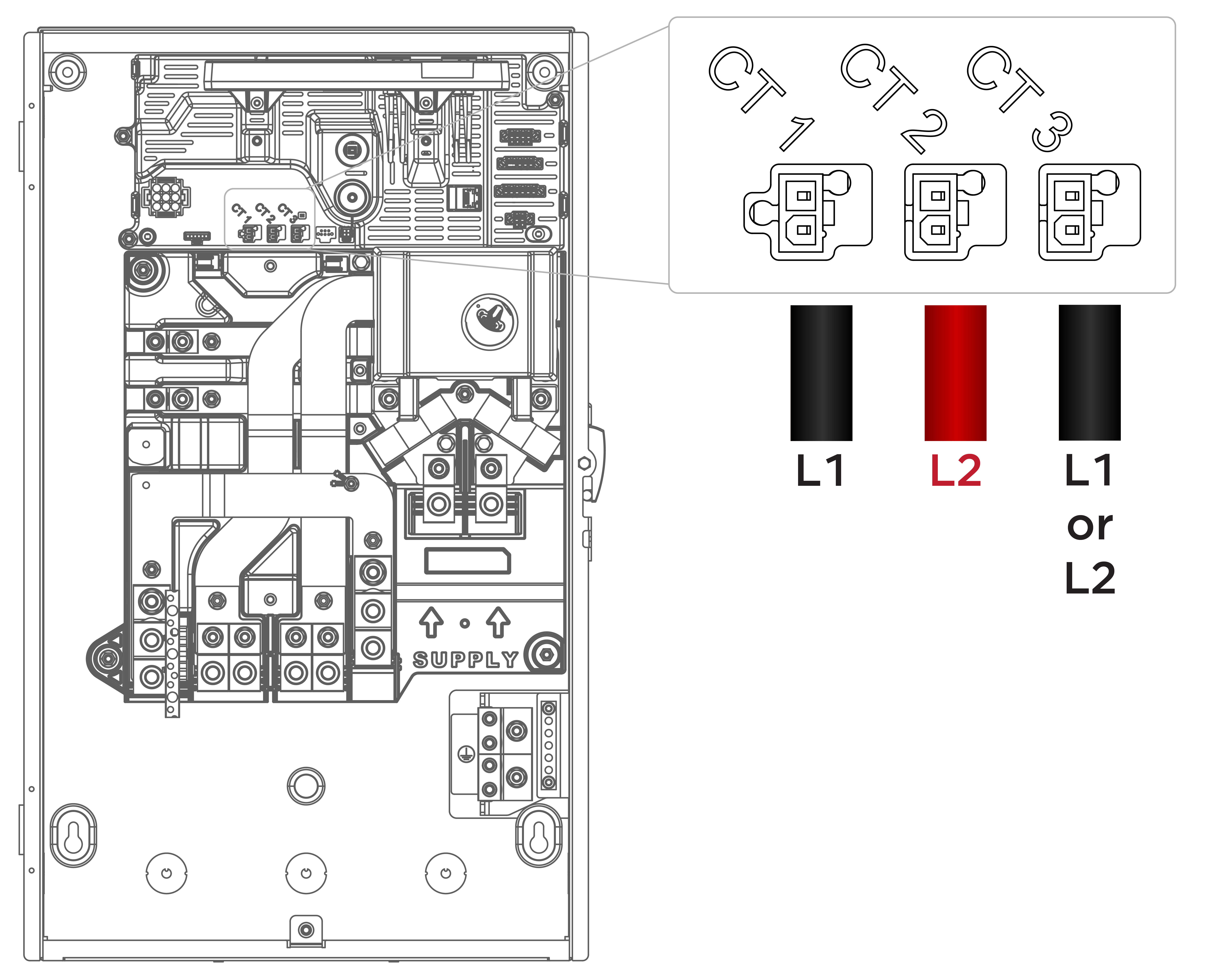
- Neurio Remote Energy
Meter with Neurio CTs:
CT1 Line 1 CT2 Line 2 CT3 Line 2 CT4 Line 1 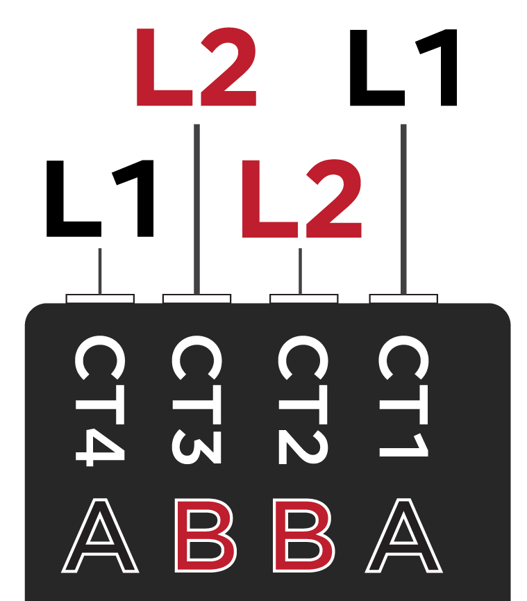
- Backup Gateway 2 with
Tesla 100 A CTs:
- Verify the CT is measuring the correct phase.
- Ensure the CT has been placed in the correct location and is measuring the
correct conductor(s):
- Verify the CT is clamped properly
around the intended conductor(s). WarningBefore installing, disconnecting, and/or adjusting CTs, ensure the circuits being measured are not energized and the system is completely powered down. Failure to de-energize the system may compromise operator and equipment safety.
- Verify the CT is not capturing any
other conductor(s).NoteIf a site has multiple inverter outputs and their conductors are being grouped, ensure every conductor is captured.
In the first example below, the CT captures the (3) L1 conductors for three solar inverters. In the second example, the CT captures (2) solar inverter conductors and (1) hot tub conductor, leaving the third solar inverter conductor uncaptured.
Figure 3. Solar CT Measuring all PV (top) and Solar CT Measuring Partial PV and a Non-Solar Load (bottom) 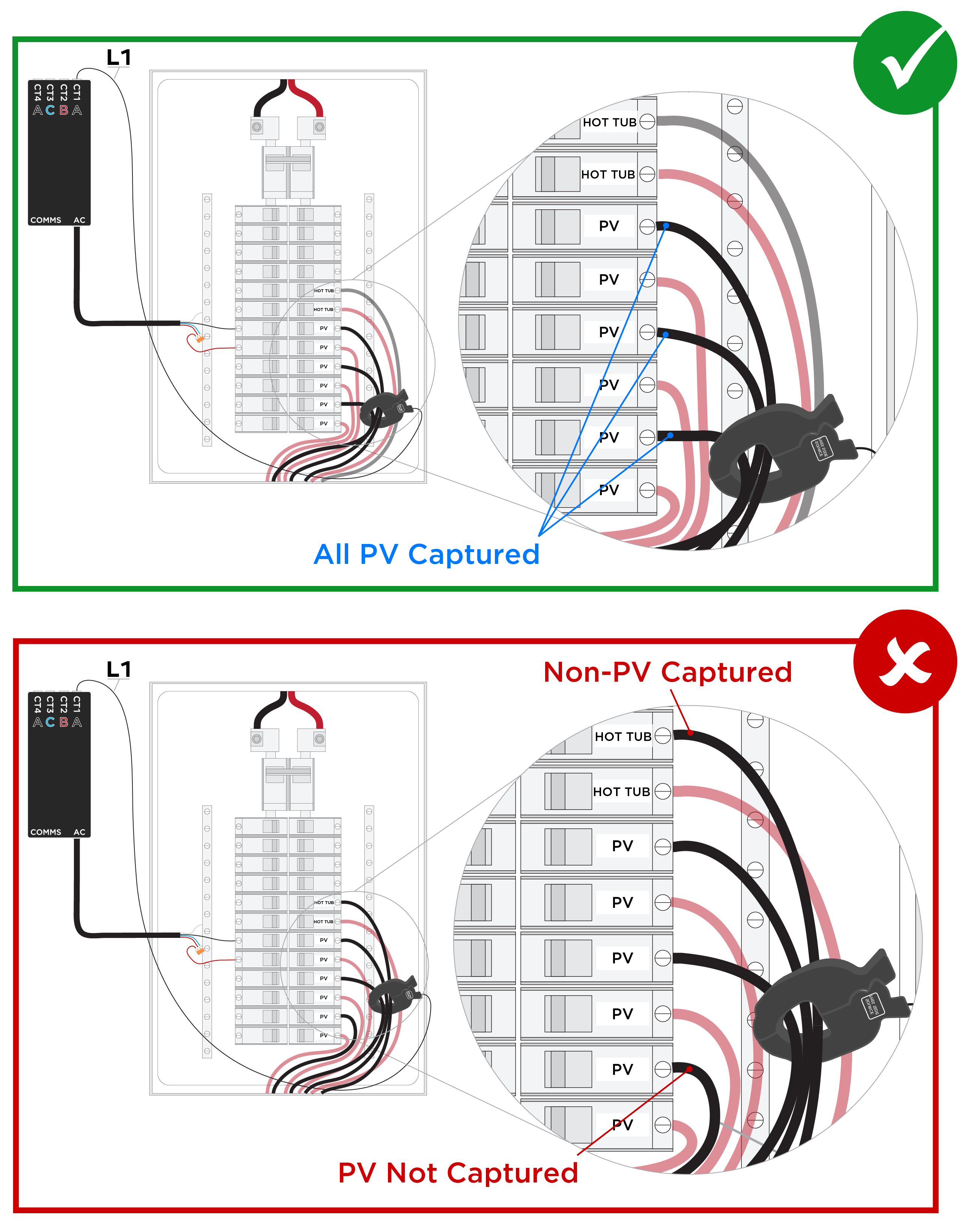
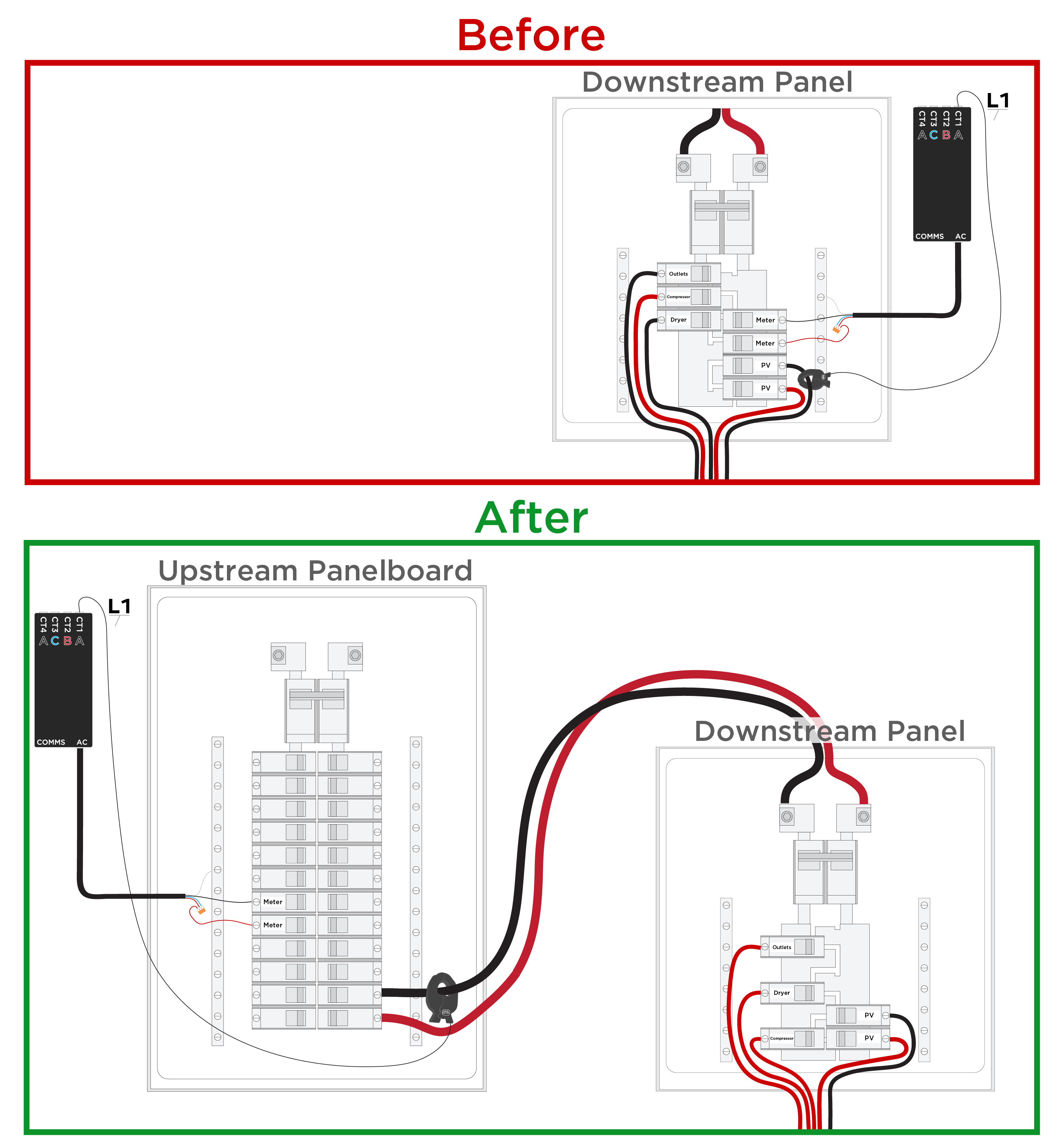
- If solar is in a generation
panel where the only conductors are solar, the entire generation panel can be
measured:
- If there are additional 120V loads in the downstream panel, move them all to the same phase (in the example below, they are moved to L2).
- Move the Neurio meter and CTs to the upstream panel and place the CT on the downstream panel feeder, choosing the opposite phase (in the example below, the CT is placed on L1).
- Configure the CT as Solar (1CTx2).
- Verify the CT is clamped properly
around the intended conductor(s).