MCI Diode Test and Resistance Test (MCI Health Tests)
The following tests are used to confirm MCIs are functioning as expected.
- Before removing MCIs from an array to test them, confirm MCIs have been installed per the Powerwall+ / Tesla Solar Inverter installation manual to comply with RSD code requirements (1 MCI per every X modules, or 1 MCI on ends of strings, depending on the system being installed, see manual for details).
- When identifying which MCI(s) are
faulty, remove all MCIs from the array and perform the MCI health tests listed
below. Replace any faulty MCI with a known healthy MCI when installing the MCIs
in the array again.CAUTIONIf an array has faulty MCI(s) and there are not sufficient healthy MCIs to replace them, ensure the system is left OFF until the return visit has been completed and the required number of MCIs has been installed.
Note
Take photos of all readings while troubleshooting.
- Tesla installers: Upload these screenshots to the JCO in the Tesla One app
- Certified Installers: Upload these screenshots to the Channel Support Intake Form (see Expectations for Certified Installers Contacting Tesla Support for more information)
MCI Diode Test
The MCI diode test is used to ensure the diode in the MCI is functioning as expected.
To perform a diode test:
- Connect the red lead of a digital multimeter to the MC4+ lead of an MCI.
- Connect the black lead of the digital multimeter to the MC4- lead of the MCI.
- Turn the dial on the
multimeter to the Ohm symbol, then push the SEL button twice to
enter Diode testing mode. The Diode test symbol will appear on the display.
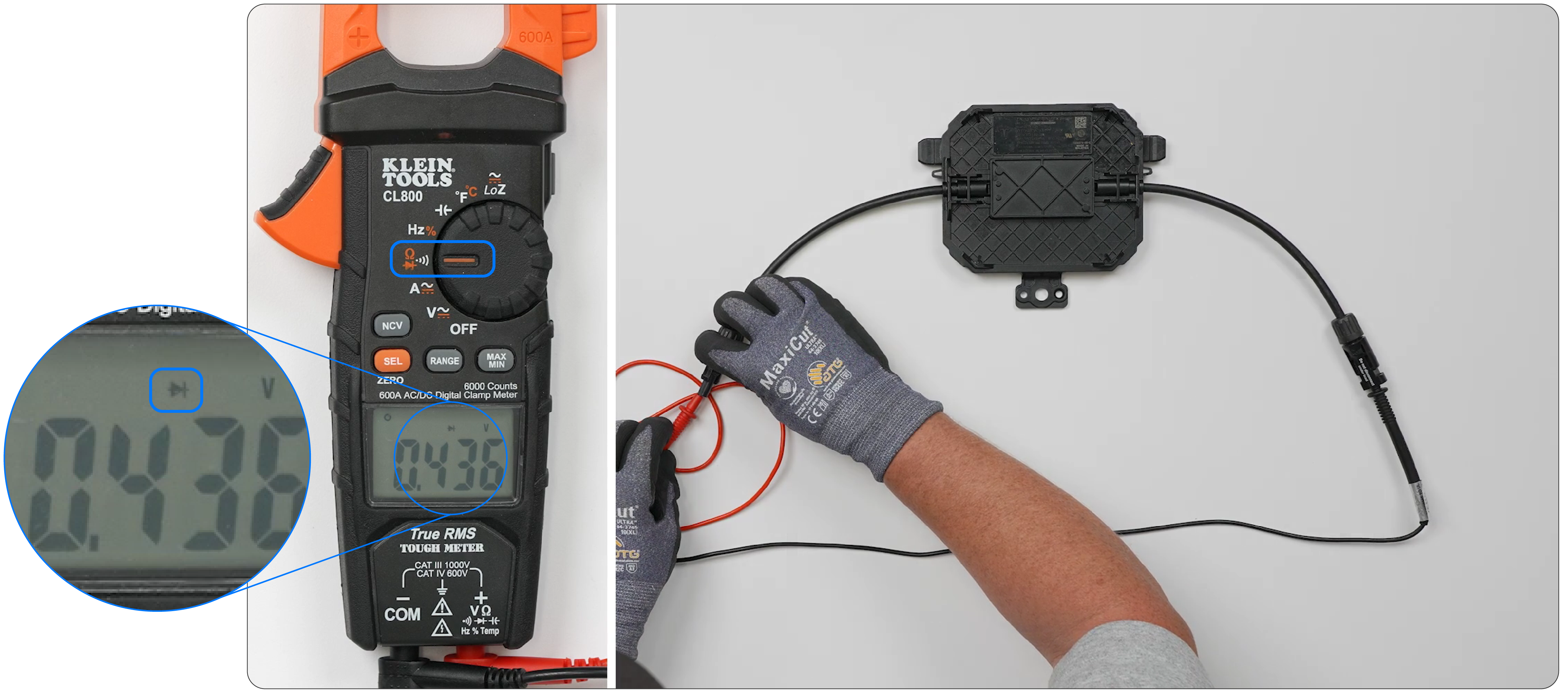
- Review the reading on the
digital multimeter. It should be approximately 0.5 V.
- A reading greater than 1 V means the MCI failed open.
- A reading less than 0.25 V means the MCI failed short.
- A reading of 'OL' indicates there is a missed connection or FET solder joint in the MCI.
If a suspected non-functional MCI is found in the field, confirm the MCI is the issue by swapping out the MCI and verifying the issue has been fixed. Swap the original unit back in again to see if the issue remains fixed, or if the issue occurs again with the original MCI installed.
Note
Avoid excessive stress to wires
when performing the diode test. Faulty connection of press fit pins will result
in an 'OL' reading the multimeter. If this occurs, manipulate the wires and
measure again. For an optional additional check, if the diode test initially
failed and now passes, try it again to see if wire management did indeed fix the
issue.
MCI Resistance Test
To perform an MCI resistance test:
- Connect the red lead of a digital multimeter to the MC4- lead of an MCI.
- Connect the black lead of the digital multimeter to the MC4+ lead of the MCI.
- Turn the dial on the multimeter to the Ohm symbol, then push the SEL button once to enter Resistance testing mode. The Resistance test symbol will appear on the display.
- Review the reading on the digital multimeter. It should be > 1 MΩ.
Perform a visual inspection of the MCI, looking for deformation, physical damage, and/or damage to connector integrity. If any issues are found during the visual inspection, or if the MCI fails the resistance test, replace the MCI.