Determine True String VOC
True String VOC Test Overview
The following procedure closes the MCIs (also referred to as bypassing the MCIs) to check the VOC of the string, confirming that the string has been wired correctly.
Note
Perform this testing after
wires have been pulled through but before they have been landed at the Powerwall+ / Tesla
Solar Inverter.
Note
This test must be completed on PV strings before they are to be combined
(paralleled).
Required Tools:
- Insulation Resistance Tester in 1000 V test mode (Tesla recommends Klein ET600)
- Safely shut the system down:
- Initiate Rapid
Shutdown:
- For Powerwall+, push the System Shutdown Switch if one is present, then turn the Enable switch OFF.
- For Tesla Solar Inverter, turn the AC disconnect OFF if one is present, then open the Solar Inverter circuit breaker.
- Open the Powerwall+ / Tesla Solar Inverter circuit breaker (turn OFF) if not already done.
- Remove the DC Isolator connector.
Figure 2. Tesla Solar Inverter DC Isolator 
- Wait 30 seconds before
proceeding with any work.WarningConfirm Powerwall+ / Tesla Solar Inverter is de-energized before proceeding. Confirm the breaker is open (OFF) and solar production is disabled in Tesla One.
- Initiate Rapid
Shutdown:
- Plug the positive and negative
meter tester leads into the meter. For combination insulation resistance and
multimeter testers, insert the test leads into the designated insulation testing
ports.
- Set the tester to 1000 V mode.
- Disconnect both (positive and
negative) conductors to test a string. The conductors can be disconnected from
the inverter (on the ground) or on the roof.NoteParalleled strings must be tested independently. This must be done on the roof, and can be done by undoing Y-connectors or removing jumpers inside the combiner box.NoteFor very short strings of two modules, test the short string together with a string that passes the test. Short strings may not be able to be tested by themselves.
- Connect the positive tester lead (red) to the positive conductor.
- Connect the negative tester lead (black) to the negative conductor.
Figure 3. Testing Conductors on the Ground (at Inverter) 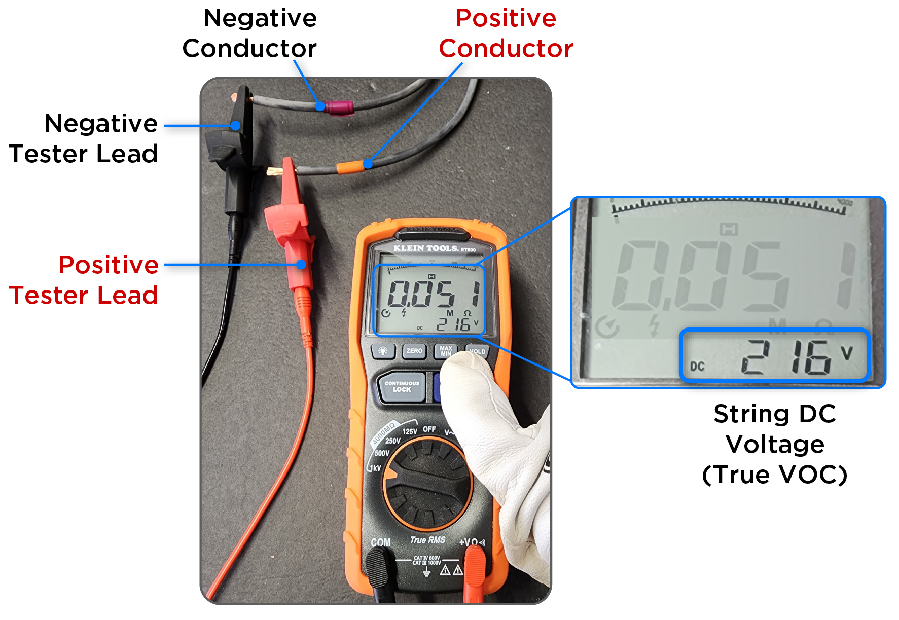
Figure 4. Testing Conductors on the Roof 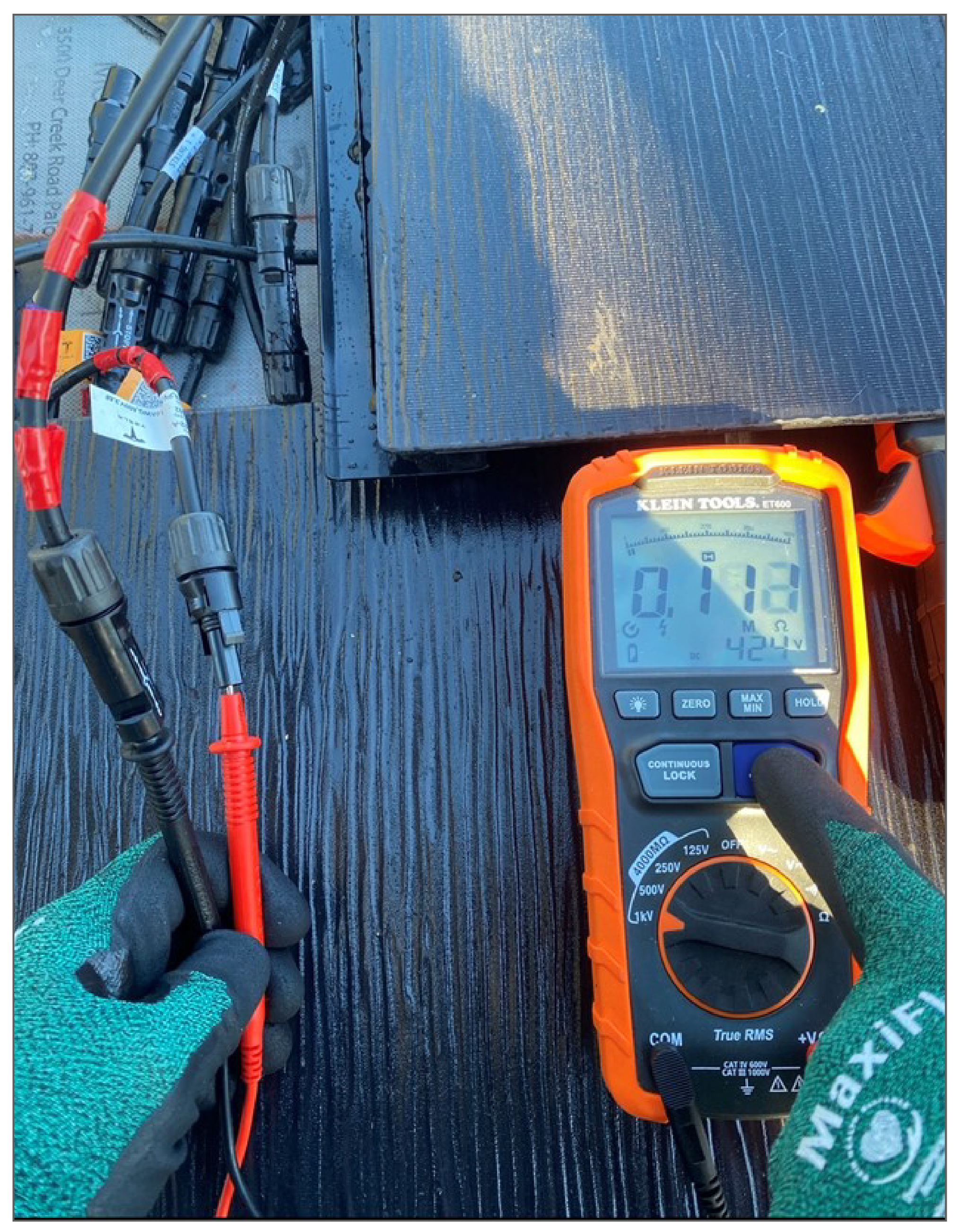
- Press and hold the TEST button to begin the test. Allow the reading to
stabilize before recording the measurement (take the resistance value while
STILL holding the TEST button).NoteKeep the test leads connected to the circuit until it is completely discharged, and the display shows near zero volts.
- If any string does not display
the expected string
voltage (see planset), inspect the wiring of the entire array to ensure
it matches the design:
- Confirm that all wiring has been connected correctly
- Confirm that no connections have been missed
- Confirm that each home run has been properly labeled based on its source (for instance, string 1 on the planset is labeled correctly as string 1 on the roof and at the inverter)
- Confirm the crimp made on each MC4 head was done correctly (see Stäubli MC4 and MC4-Evo 2 assembly tutorial)
- Confirm that any MC4 connections that were added (due to breaks or extensions) are tied to the correct home run or panel lead
- If PV jumpers were used, confirm they are wired correctly. For example:
- One string includes two arrays on two separate mounting planes. Confirm the positive from the MP1 array has been landed at the negative from the MP2 array
- A common error in this scenario is to land positive to positive and negative to negative, which is incorrect when manually installing MC4 heads
- If a junction box is present, double check all internal connections
- Test VOC before making any parallel connections
- The VOC should match across strings before they are combined
- If the voltage of one string is lower than the string it will be
combined with, the VOC of the combined string will be
the lower outputNoteIt is possible to misinterpret this test result, obtained with the tester in 1 kV mode, as being the result of the PV strings being mixed up. To avoid this confusion, test VOC before combining strings.